P/N 960-000164R_Rev. 3 {EDP #213631} © 2018, JAPAN CASH MACHINE CO., LTD.
Section 4 iPRO-RC™ Series Banknote Recycler Disassembly/Reassembly
Impeller and Stop Roller Removal
To remove the Impeller and the Stop Roller,
proceed as follows:
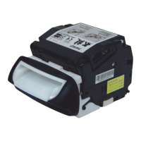
1. Remove the four (4) E-Rings (Figure 4-31 a
1
to
a
4
) retaining the two (2) Flappers (Figure 4-31 b
1
& b
2
) in place, and remove the four (4) Plastic
Pushing Bearings (Figure 4-31 c
1
to c
4
) and Flap-
pers from the RC Course Assy..
2. Remove each of the single (1) Return Springs
(Figure 4-32 a) from th
e RC Course Assy. mount-
ing hooks (Figure 4-32 b).
3. Remove the four (4) E-Rings (Figure 4-33 a
1
to
a
4
) retaining the two (2) Shafts (Figure 4-33 b
1
&
b
2
) in place.
4. Remove the two (2) Shafts, the four (4) related
Beari
ngs (Figure 4-33 c
1
to c
4
) and the four (4)
Poly Vinyl Sliders (Figure 4-33 d
1
to d
4
) from the
RC Course Assy..
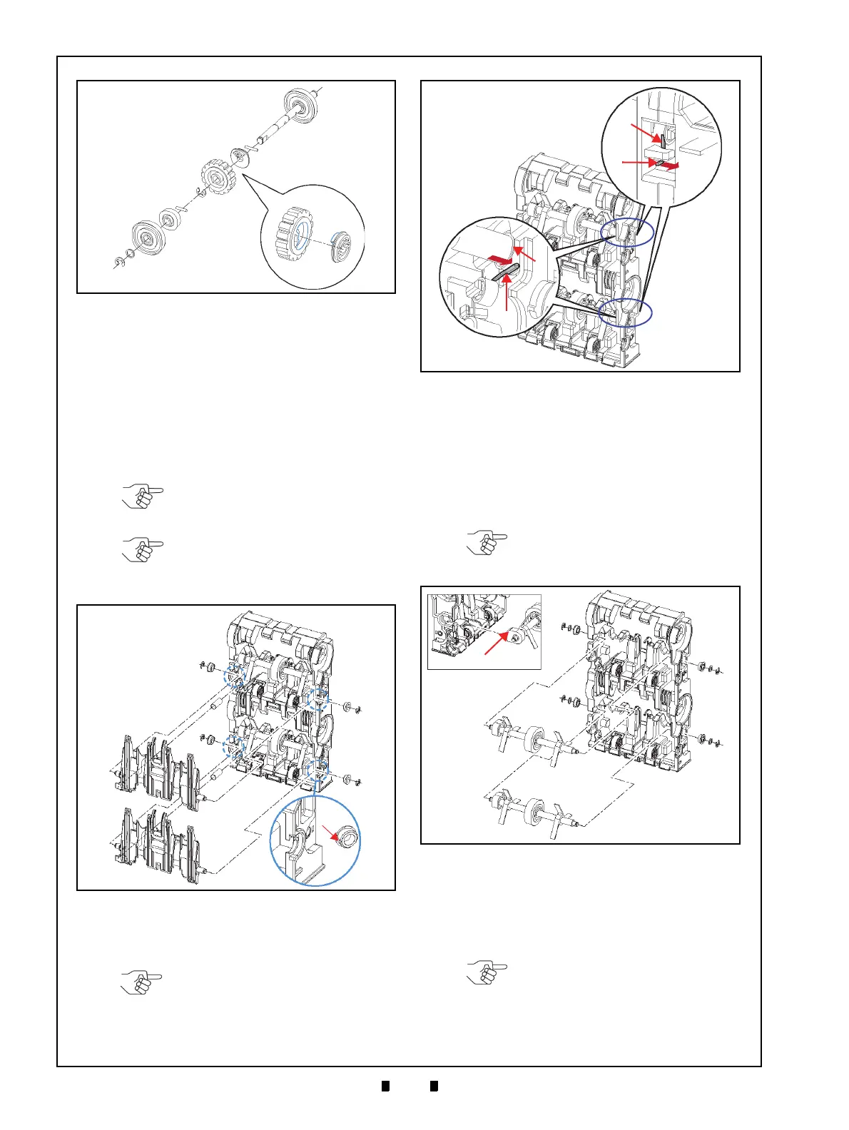
5. Remove the two (2) Impellers (Figure 4-34 a
1
&
a
2
) and the One-Way Holder (Figure 4-34 b) from
the Shaft (Figure 4-34 c).
6. Remove the single (1) E-Ring (Figure 4-34 d) an
d
the Stop Roller (Figure 4-34 e) from the
Shaft.
Figure 4-30 Feed Roller Removal
Figure 4-30 Feed Roller Removal
NOTE: Be careful that the Springs
(Figure 4-31 d
1
& d
2
) are not lost
when removing the Flappers.
NOTE: When re-assembling the
Plastic Bearing Bushing, align the
groves to the cut area in the RC
Course Assy. (Figure 4-31 f).
Figure 4-31 Flapper Removals
d
1
d
2
a
1
a
2
a
3
a
4
b
1
b
2
c
1
c
2
c
3
c
4
f
Groove
Figure 4-31 Flapper Removals
NOTE: Replace each Spring back
(Figure 4-32 c) into its related
Bearing (Figure 4-32 d) position
when re-assembling Unit.
Figure 4-32 Spring Removals
Figure 4-32 Spring Removals
NOTE: Position the slanted cut
surface of the One-Way Holder up
when re-installing it (Figure 4-33 e).
Figure 4-33 Impeller Shaft Removals
a
1
a
2
a
3
a
4
b
1
b
2
c
1
c
2
c
3
c
4
e
d
1
d
2
d
3
d
4
Oblique Cut
Figure 4-33 Impeller Shaft Removals
NOTE: Be careful that the Parallel
Pin (Figure 4-34 f) is not lost.