P/N 960-000164R_Rev. 3 {EDP #213631} © 2018, JAPAN CASH MACHINE CO., LTD.
Performance Tests iPRO-RC™ Series Banknote Recycler Section 6
17. Remove power from the iPRO-RC. Set all the
iPRO-RC Transport DIP Switches to
OFF.
18. Turn the iPRO-RC™ Power Switch to
ON. The
Firmware downloaded to the iPRO Transport
Unit will begin transferring data to the
iPRO-RC™ Unit.
19. Confirm that the iPRO-RC™ LED is lit a steady
Ye
ll ow Color during the download. The LED will
light a steady Green Color when the Firmware
download to the iPRO-RC™ is complete.
This completes the iPRO-RC™ Firmware
installation procedure.
Calibration
This section provides instructions for performing
Sensor calibration within the iPRO-RC™ Unit.
When to Calibrate
Calibration should be performed if the following
conditions occur:
– When removing and replacing each Sensor.
– When dirt is adhering to Sensors. Perform
Calibration after cleaning the Sensors and
the Rollers. (See “Cleaning Procedure” on
page2-10 of this Service Manual.)
– When the Banknote dispensing rate is
drastically degraded.
Calibration Tool Requirements
To identify the tool and equipment interconnects
necessary to calibrate the iPRO-RC™ Unit away
from its Host Machine, refer to Figure 6-1 “Tool
and Harness Connection” on page 6-1 of this
Section
.
iPRO-RC Reference Paper
Figure 6-22 illustrates the KS-087 iPRO-RC™
Reference Paper.
Placing the Reference Paper
The iPRO-RC™ requires only one (1) Reference
Paper (KS-087) type for calibration and perfor-
mance testing.
Insert the KS-087 Reference Paper into the iPRO™
Transport Unit’s Insertion Slot following the Cali-
bration Tool instruction (Figure 6-22).
Calibration and Testing Program
This portion provides the Calibration and Testing
Program (
iPRORC_MaintenanceSuiteEdition.exe)
Configuration. The Calibration and Testing Pro-
gram contains the following five (5) selections:
• Double Note Detection Sensor Calibration
• RC Full Sensor Calibration
• Transport Sensor Test
• Motor Test
• Model Information Input.
Sensor Calibration and Performance
Testing
Perform the following steps to initiate Sensor
Calibration and the Performance Testing processes.
1. Turn the iPRO-RC™ Power Supply OFF.
2. Set the iPRO™ Transport Unit’s 8-Position DIP
Switch
es # 1, #2, #5 & #8 to
ON (Figure 6-24 &
Figure 6-26 a).
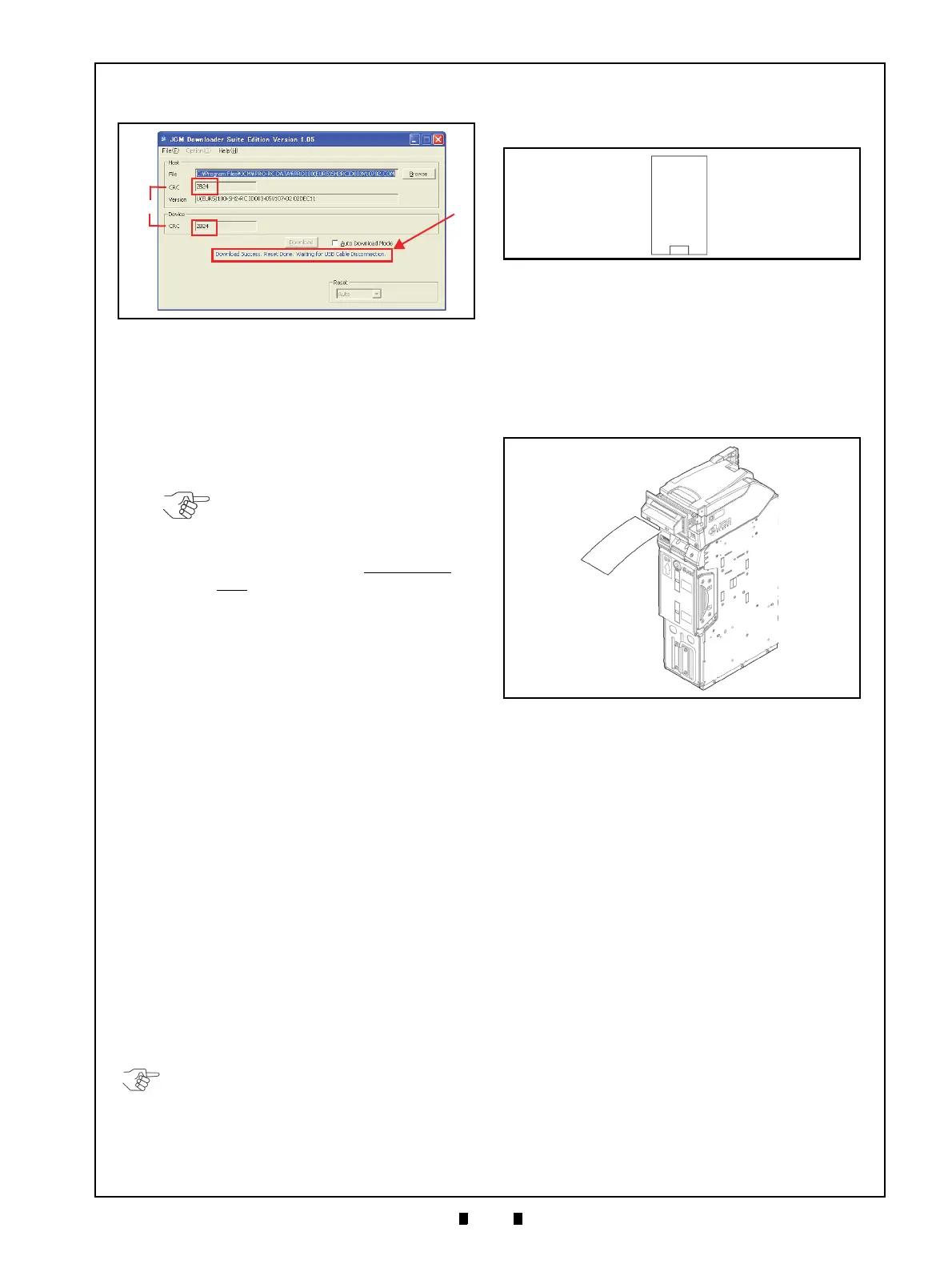
Figure 6-21 Download Completed Screen
Figure 6-21 Download Completed Screen
NOTE: If a Firmware upgrade is
unnecessary, or iPRO Transport Unit
DIP Switches #6, #7 and #8 are ON,
the Firmware downloaded to the
iPRO Transport Unit will NOT be
sent to the iPRO-RC Unit!
NOTE: When the “USB-A Terminal” connects to
a USB Hub, the iPRO-RC may not operate as
expected. Ensure that the “USB-A Terminal”
connects DIRECTLY to a PC USB Port!
Figure 6-22 KS-087 Reference Paper
Figure 6-22 KS-087 Reference Paper
Figure 6-23 Reference Paper Insertion
Figure 6-23 Reference Paper Insertion