P/N 960-000164R_Rev. 3 {EDP #213631} © 2018, JAPAN CASH MACHINE CO., LTD.
Performance Tests iPRO-RC™ Series Banknote Recycler Section 6
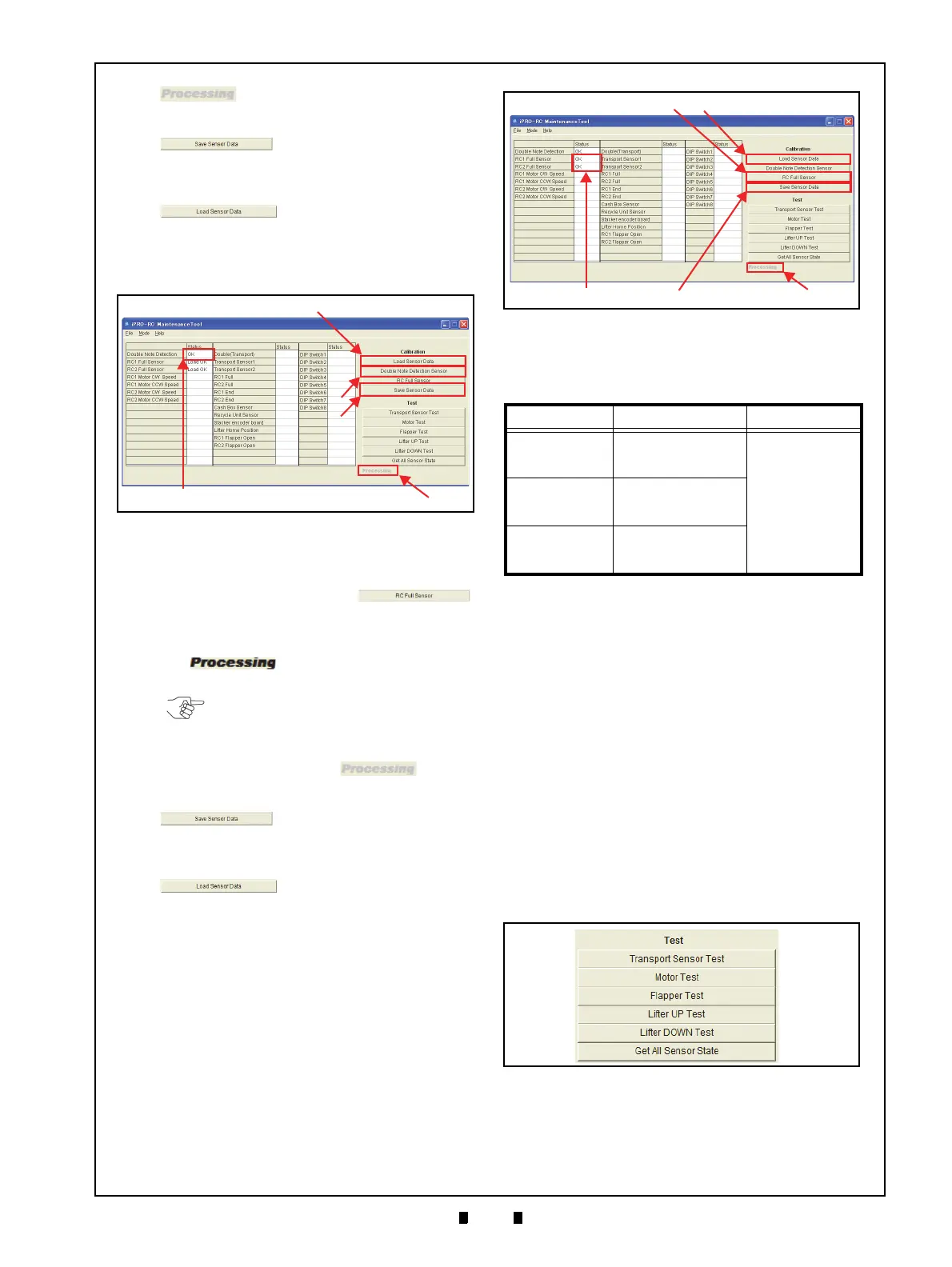
word will again turn to Grayed-out
text (Figure 6-52 b).
5. Click on the “
Save Sensor Data”
Function Screen Button (Figure
6-52 c)
to reflect the saved Status in the related
result Field.
6. Click on the “
Load Sensor Data”
Function Screen Button (Fig-
ure 6-52 d)
to read the saved Status result data.
7. Confirm that the “
OK” (Figure 6-52 e) Status text
message appears in the Status result Field next to
the Do
uble Note Detection text line label.
RC F
ULL
S
ENSOR
B
UTTON
C
ALIBRATION
1. Check that the Recycler Unit is Empty.
2. Click on the “
RC Full Sensor”
Calibration Screen Button (Figure 6-53 a).
3. Confirm that the iPRO-RC™ Unit LED indicates
a stea
dy Green Color. The Bold Text “
Process-
ing
” word appears during the Test’s
performance (Figure 6-53 b).
4. When the RC Full Sensor Calibration is complete,
the Bol
d Text “
Processing” word
will turn to Grayed-out text (Figure 6-53 b).
5. Click on the “
Save Sensor Data”
Screen Button (Figure 6-53 c)
to reflect the saved Status in the related result
Fi
eld.
6. Click on the “
Load Sensor Data”
Screen Button (Figure 6-53 d)
to read the saved Status result data.
7. Confirm that the “
OK” text message (Figure 6-53
e) appears in the Status result Field next to the
RC1 Full Sensor and the RC2 Full Sensor text
line labels.
Table 6-1 lists the Sensor Calibration Items, their
descriptions and their resulting configurations.
Individual Performance Test
The six (6) Function Buttons shown in Figure 6-54
are for activating Calibration tests for the following
functions:
• Transport Sensor Test:
Checks the Transport movement Sensor
• Motor Test:
C
hecks the Motor Normal/Reverse rotation
• Flapper Test:
Checks the Flapper’s movement
• Lifter UP Test:
Checks the Lifter’s upward movement
• Lifter DOWN Test:
Checks the Lifter’s downward movement
• Get All Sensor States:
Reads all of the Sensor’s conditions.
Click on the desired Test Function Screen Button to
begin each Performance Test.
The Test begins, and will finish automatically. The
“
Processing” display message appears in bold
Figure 6-52 Double Note Detection Sensor
Figure 6-52 Double Note Detection Sensor
NOTE: The LED will flash at a Green
Color Rate when an abnormal condition
occurs!
Table 6-1 Sensor Calibration Configuration
Item Description Result
Double Note
Detection Sensor
Indicates the Double
Note Detection
Sensor’s Condition
Load OK = Current
Calibration Value
Read Completion
OK = Calibration
Success
NG = Abnormal
Condition
Occurred
RC1 Full Sensor
Indicates the RC1 Full
Sensor’s Calibration
Condition
RC2 Full Sensor
Indicates the RC2 Full
Sensor’s Calibration
Condition
Figure 6-53 RC Full Sensor
Figure 6-53 RC Full Sensor
Figure 6-54 Test Function Screen Buttons
Figure 6-54 Test Function Screen Buttons