P/N 960-000164R_Rev. 3 {EDP #213631} © 2018, JAPAN CASH MACHINE CO., LTD.
iPRO-RC™ Series
Banknote Recycler
Section 4
This section provides disassembly and reassembly
instructions for the iPRO-RC™ Series Banknote
Recycler (iPRO-100-SH2-RC; iPRO-RC™). This
section contains the following information:
• Tool Requirements
• Power Source Circuit Board Removal
• Lifter Motor Encoder Circuit Board Assy.
Removal
• Recycler CPU Circuit Board Assy. Removal
• Emission Side Double Note Sensor Removal
• Lifter Motor Assy. Removal
• Upper & Lower Full Sensor, PT/Upper &
Lower End Sensor LED Removal
• Upper & Lower Full Sensor, LED/Upper &
Lower End Sensor, PT/Lifter Home Position
Sensor LED & PT Removal
• Upper & Lower Flapper Pusher Lever Solenoid
Removal
• Flapper Open & Close Circuit Board Removals
• Banknote Transaction Sensor/Transport Unit
Encoder Circuit Board & Double Note Sensor
PT Removal
• Banknote Transaction Sensor & Cash Box
Sensor Circuit Board Removal
• Recycler Encoder Circuit Board Removal
• Upper & Lower Recycler Transport Motor
Assy. Removal
• Timing Belt Removal
• Pick Roller Removal
• Feed Roller Removal
• Impeller/Stop Roller Removal
• Pusher Plate O-Ring Removal
• Roller Timing Belt & O-Ring Removal
• Pusher Plate Re-installation
Tool Requirements
The following tools are required to perform
iPRO-RC™ disassembly and reassembly.
• #1 & #2 Phillips Screw Drivers
• A #2, #2.5, #3 and #4 E-Clip Holder
• Needlenose Pliers
• Tweezers
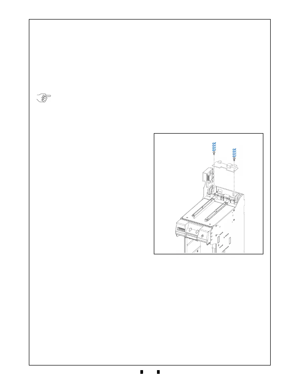
Power Source Board Removal
To remove the Power Source Circuit Board, pro-
ceed as follows:
1. Separate the Transport Unit, Recycler Box Unit
and Cash Box Unit from the Frame Housing.
2. Remove the two (2) Mounting Screws (Figure 4-1
a
1
& a
2
) retaining the Power Source Circuit Board
(Figure 4-1 b) in plac
e, and take the Power Source
Circuit Board off the top of the Frame.
Lifter Motor Encoder Board Assy
Removal
To remove the Lifter Motor Encoder Circuit Board
Assembly, proceed as follows:
1. Remove the four (4) Mounting Screws (Figure 4-
2 a
1
to a
4
) retaining the UBA/iPRO-RC Upper
Frame in place (Figure 4-2 b),
and lift the Upper
Frame up and off the Frame top.
2. Remove the single (1) Mounting Screw (Figure 4-
2 c) ret
aining the Lifter Motor Encoder Circuit
Board Assembly in place (Figure 4-2 d); unpl
ug
the single (1) Connector (Figure 4-2 e), and th
en
remove the Lifter Motor En
coder Circuit Board
Assembly from the Frame.
NOTE: Calibration is required after
reassembly (Refer to “Calibration” on
page 6-5).
Figure 4-1 Power Source Circuit Board
Removal
Figure 4-1 Power Source Circuit Board Removal