P/N 960-000164R_Rev. 3 {EDP #213631} © 2018, JAPAN CASH MACHINE CO., LTD.
Section 2 iPRO-RC™ Series Banknote Recycler Installation
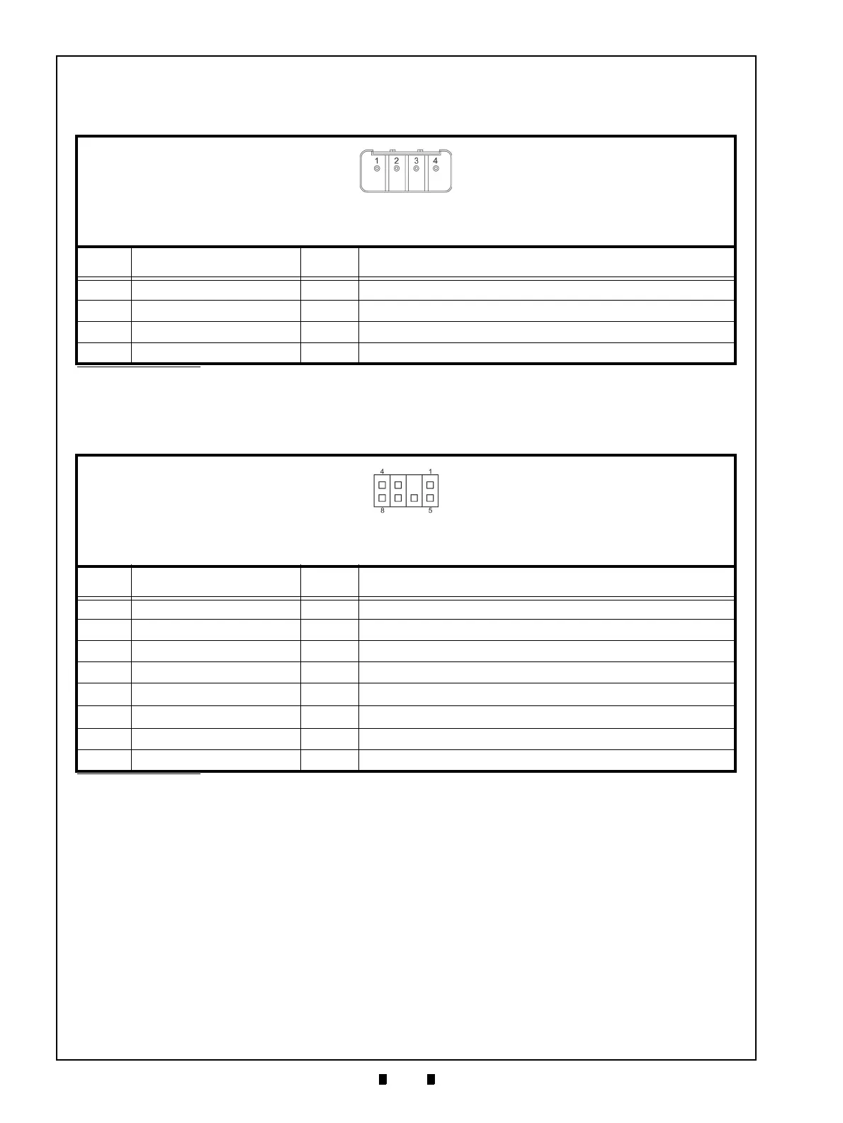
Connector Pin Assignments (Continued)
Table 2-9 lists the iPRO-RC™ Power Supply Pin Assignments.
Connector Pin Assignments (Continued)
Table 2-10 lists the iPRO-RC™ Front Panel Bezel Interface Connection Pin Assignments.
Table 2-9 Power Supply Pin Assignments
Header Type: 53426-0410 (MOLEX)
Contact Type: 50351-8100 (MOLEX)
Housing: 51103-0400 (MOLEX)
Recommended Wires: Slit Wire UL1007 AWG #22-24
Pin No. Signal Name
I/O
*
*. I/O (input/output) is the terminal as viewed from the Banknote Recycler’s backside.
Function
1 +24V Power - +24V DC Power Supply
2 +24V Power - +24V DC Power Supply
3 GND (Power) - 0V DC Power
4 GND (Power) - 0V DC Power
Table 2-10 Front Panel Bezel Interface Connection Pin Assignments
Header Type: RF-H08(07)2SD-1110 (JST)
Contact Type: RF-SC2210 (JST)
Housing: RF-08 (JST)
Recommended Wires: Slit Wire UL1007 AWG #24-26
Pin No. Signal Name
I/O
*
*. I/O (input/output) is the terminal as viewed from the Banknote Recycler’s backside.
Function
1 NC - No Connection
2 NC - No Connection
3 NC - No Connection
4 NC - No Connection
5 +13V (Power) -
+13V DC Power (from the iPRO
™)
6 GND (Power) -
0V DC Power (from the iPRO™)
7 LED Power - LED Drive Line (Anode)
8 LED - LED Drive Line (Cathode)