P/N 960-000164R_Rev. 3 {EDP #213631} © 2018, JAPAN CASH MACHINE CO., LTD.
Disassembly/Reassembly iPRO-RC™ Series Banknote Recycler Section 4
Recycler Encoder Board Removal
To remove the Recycler Encoder Circuit Board,
proceed as follows:
1. Remove each of the four (4) Mounting Screws
(Figure 4-19 a
1
to a
4
& b
1
to b
4
) retaining two (2)
Rear Transport Gear Covers (Figure 4-19 c
1
& c
2
)
in place, and take the Rear Transport Gear Covers
of
f of the Rear Transport Assembly.
2. Remove each of the single (1) Mounting Screws
(Figure 4-19 d
1
& d
2
) retaining the two (2) Recy-
cler Encoder Circuit Boards (Figure 4-19 e
1
& e
2
)
in place, and unplug each of the related single
(1)
Signal Connector’s (Figure 4-19 f
1
& f
2
) from
each Board; then remove the Recycler Encoder
Circuit
Boards from the Rear Transport Assem-
bly.
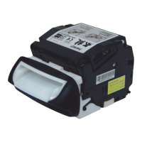
Upper & Lower Recycler Transport
Motor Assy Removal
To remove the Recycler Transport Motors, proceed
as follows:
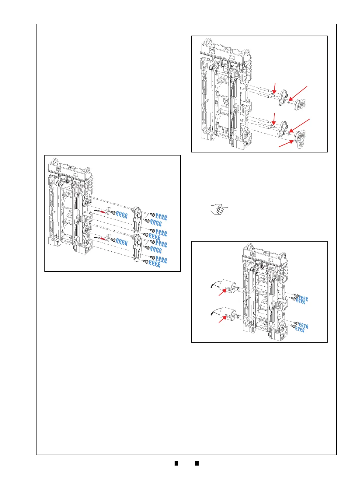
1. Remove the nine (9) Gears (Figure 4-20 a
1
to a
9
),
the six (6) Shafts (Figure 4-20 b
1
to b
6
) and the
two (2) Poly Vinyl Sliders (Figure 4-20 c
1
& c
2
)
from the Rear Transport Assembly.
2. Remove the two (2) Mounting Screws (Figure 4-
21 a
1
, a
2
& b
1
, b
2
) retaining the two (2) Recycler
Transport Motors (Figure 4-21 c
1
& c
2
) in place;
then remove the Recycler Transport Motor from
th
e Rear Transport Assembly.
Figure 4-19 Recycler Encoder Circuit Board
Removal
a
1
a
3
a
4
b
1
b
3
b
4
c
1
c
2
f
1
f
2
d
1
d
2
e
1
e
2
a
2
b
2
Figure 4-19 Recycler Encoder Circuit Board
Removal
Figure 4-20 Gear & Shaft Removal
a
1
a
2
a
3
a
5
a
6
a
7
a
8
a
9
b
1
b
2
b
4
b
3
b
6
a
4
c
1
c
2
b
5
Figure 4-20 Gear & Shaft Removal
NOTE: When re-assembling the
Motors, ensure that the holes on the
Motors (Figure 4-21 d
1
& d
2
) are
visible from the front side of the Rear
Transport Assembly.
Figure 4-21 Recycler Transport Motors
Removal
Figure 4-21 Recycler Transport Motors Removal