P/N 960-000164R_Rev. 3 {EDP #213631} © 2018, JAPAN CASH MACHINE CO., LTD.
Appendix A iPRO-RC™ Series Banknote Recycler Troubleshooting
iPRO-RC Recycler Unit Width and
Length Guide Replacement
Procedure
The iPRO-RC™ Width and Length Guides located
in the Recycler Unit need to be replaced by a
trained Engineer or Technician using the following
Procedures:
Length Guide Replacement
To replace the Length Guide in the Recycler Unit,
proceed as follows:
1. Use the supplied Key to unlock the Recycler Unit
Door (Figure A-1 a) and open the Door.
2. Remove the four (4) Screws retaining the Length
Guide in place (Figure A-2 a).
3. Lift the Length Guide upward,
as indicated by
Graphic Arrow A in Figure A-2.
4. Slide the Length Guide in the direction indicated
by Graphi
c Arrow B, as shown in Figure A-2.
5. Lift the Length Guide upward again,
as indicated
by Graphic Arrow C, and lift the Length Guide up
and off of the Recycler Unit Door.
6. Remove the two (2) Screws (Figure A-2 d) fr
om
the removed RC Length Guide.
7. Remove the L Guide Assist Strip (Figure A-2 e)
and install the Length Guide replacement.
Length Guide Installation
To install a new Length Guide into the Recycler
Unit, proceed as follows:
1. Place the new Length Guide in the direction
indicated by Graphic Arrow
A in Figure A-3a.
2. Slide the Length Guide in the direction indicated
by
Graphic Arrow B, and align it to the edge of
the RC Recycler Door (Figure A-3 a).
3. Install the four (4) Length Guide Mounting
Scr
ews (Figure A-3 b) fo
r re-assembly.
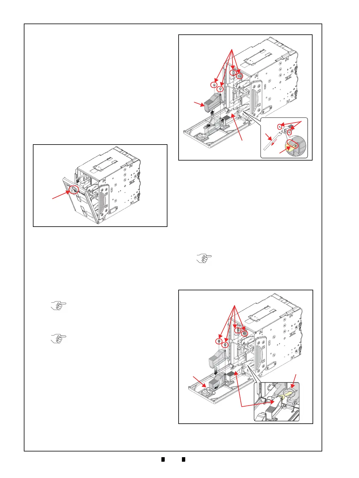
Figure A-1 Opening the Recycler Unit Door
Figure A-1 Opening the Recycler Unit Door
NOTE: Remove both RC1 (Figure A-
2 b) and RC2 (Figure A-2 c) Length
Guides during the same procedure.
NOTE: When installing the L Guide
Assist Sheet, be sure that convex
portions of the Length Guide fit into
the holes provided for them on the
right and the left sides of the L Guide
Assist Strip (Figure A-2 f).
Figure A-2 Length Guide Removal
Figure A-2 Length Guide Removal
NOTE: When installing the RC2
Length Guide (Figure A-3 c), insert
the L Guide Assist Strip onto the Door
(Figure A-3 d), to complete this
procedure.
Figure A-3 New Length Guide Installation 1
Figure A-3 New Length Guide Installation 1