P/N 960-000164R_Rev. 3 {EDP #213631} © 2018, JAPAN CASH MACHINE CO., LTD.
Section 4 iPRO-RC™ Series Banknote Recycler Disassembly/Reassembly
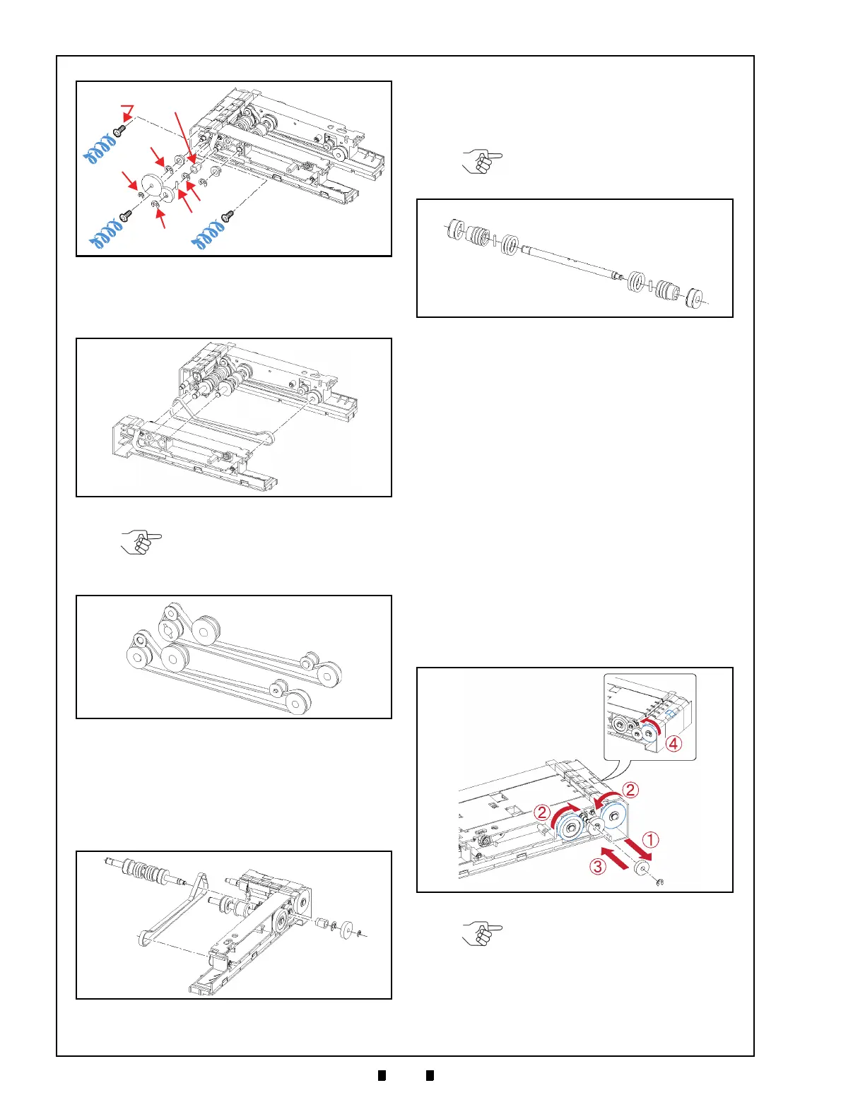
4. Separate Box Gear A (Figure 4-39 a) from the
Pusher Mechanism, and remove the Timing Belt
insi
de (Figure 4-39 b).
5. Remove the two (2) E-Rings (Figure 4-41 a
1
&
a
2
), the single (1) Gear (Figure 4-41 b), the single
(1) Shaft (Figure 4-41 c) and
the single (1) Bush-
ing (Figure 4-41 d)
from the Pusher Mechanism,
and then remove the Timing Belt from the
Assemb
ly (Figure 4-41 e).
6. Remove the two (2) Pulleys (Figure 4-42 a
1
& a
2
)
from the Shaft (Figure 4-42 b),
and remove the
six (6) O-Rings (Figure 4-42 c
1
to c
6
) from the
individual Pulleys.
Pusher Plate Re-installation
After re-assembling the Pusher Plate onto the
Pusher Mechanism, readjust each Gear position
as follows:
1. Remove the single (1) E-Ring (Figure 4-43 a)
and the single (1) small Gear (Figure 4-43 b)
from the Pusher Mechanism (Figure 4-43 c)
indicated by the
j Arrow.
2. Rotate the White Gear (Figure 4-43 d) and the
Black Gear (Figure 4-43 e) each in the
direction indicated by the
k Arrows until they
stop rotating.
3. Reinstall the small Gear and its related E-Ring
(removed during Step 1), as indicated by the
l
Arrow.
4. Rotate the White Gear in the direction
indicated by the
m Arrow, and make sure that
the Home Position Arm (Figure 4-43 f) meets
the surface of the Pusher Mechanism (Figure
4-43 g).
This completes the iPRO-RC™ Disassembly and
Reassembly Instructions section.
Figure 4-38 Pusher Drive Gear Removal
a
1
a
2
a
3
a
4
a
5
b
1
b
2
c
1
c
2
c
3
d
e
2
e
3
e
1
Phillips Self
Tapping
Figure 4-38 Pusher Drive Gear Removal
Figure 4-39 Pusher Timing Belt Removal 1
Figure 4-39 Pusher Timing Belt Removal 1
NOTE: The Pusher Timing Belt
should be reinstalled as illustrated in
Figure 4-40 when the Unit is being
reassembled.
Figure 4-40 Pusher Timing Belt Replacement
Figure 4-40 Pusher Timing Belt Replacement
Figure 4-41 Pusher Timing Belt Removal 2
Figure 4-41 Pusher Timing Belt Removal 2
NOTE: Be careful that the Parallel
Pins (Figure 4-42 d
1
& d
2
) are not
lost while removing the Gears.
Figure 4-42 Pulley & O-Ring Removal
Figure 4-42 Pulley & O-Ring Removal
Figure 4-43 Pusher Plate Removal
Figure 4-43 Pusher Plate Removal
NOTE: If the Gears are not correctly
re-assembled, the Home Position
Arm will not show on the surface.