P/N 960-000164R_Rev. 3 {EDP #213631} © 2018, JAPAN CASH MACHINE CO., LTD.
Disassembly/Reassembly iPRO-RC™ Series Banknote Recycler Section 4
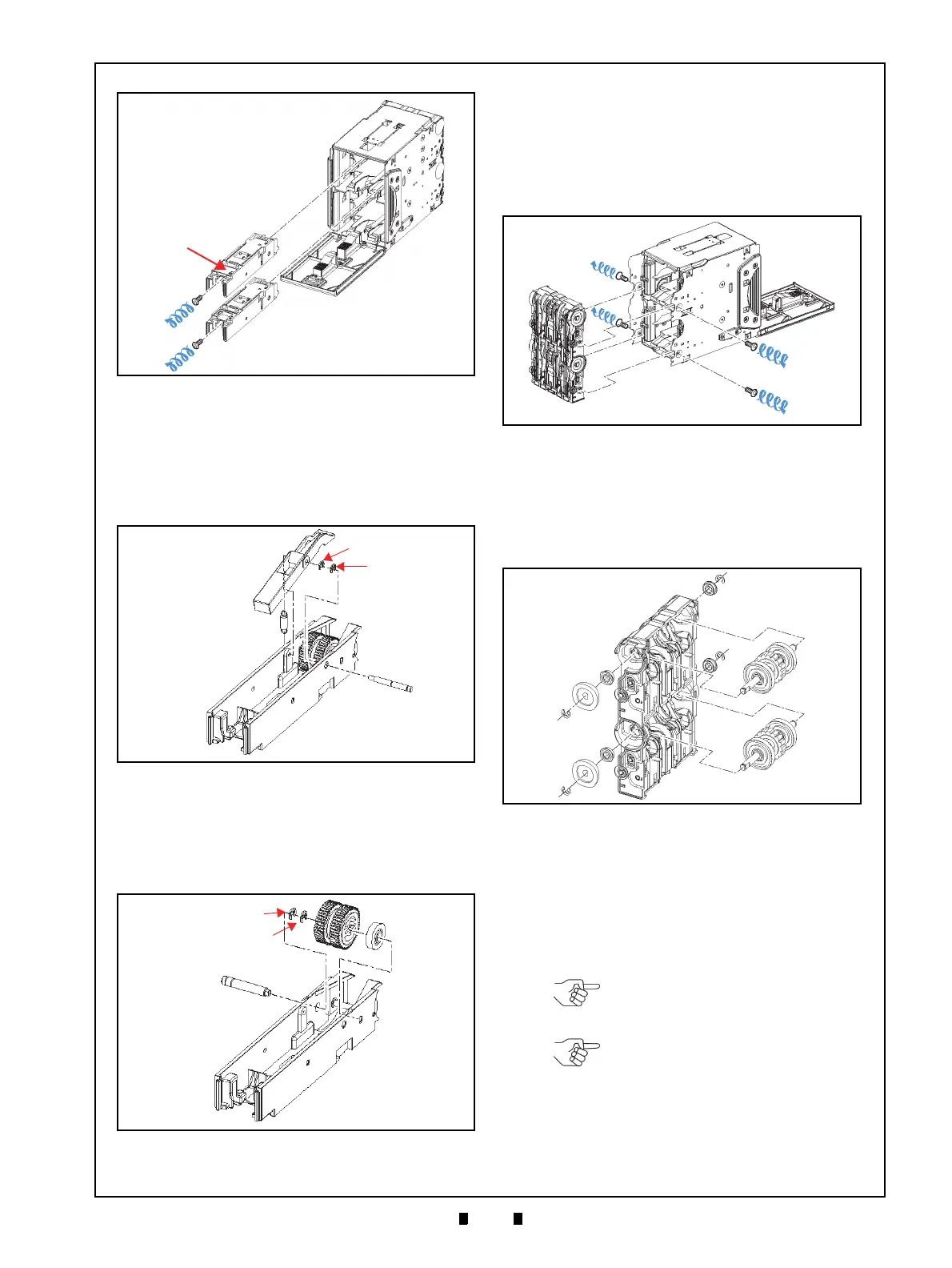
2. Remove the two (2) E-Rings (Figure 4-26 a
1
&
a
2
) retaining the Centering Guide Shaft (Figure 4-
26 b)
in place, and remove the Centering Guide
Shaft, the End Lever (Figure 4-26 c) and the
sin-
gle (1) Spring (Figure 4-26 d)
from the RC Cen-
tering Guide.
3. Remove the two (2) E-Rings (Figure 4-27 a
1
&
a
2
) retaining the RC Centering Guide Shaft (Fig-
ure 4-27 b) in place;
then remove the Centering
Guide Shaft, Pick Roller (Figure 4-27 c) and sin-
gle (1) Gear (Figure 4-27 d).
Feed Roller Removal
To remove the Feed Roller, proceed as follows:
1. Remove the four (4) Mounting Screws (Figure 4-
28 a
1
to a
4
) retaining the RC Course Assy. (Figure
4-28 b) in
place, and remove the Race from the
Cash Box Unit.
2. Remove the four (4) E-Rings (Figure 4-29 a
1
to
a
4
), the four (4) Bearings (Figure 4-29 b
1
to b
4
),
and the two (2) Gears (Figure 4-29 c
1
& c
2
); then
pull the two (2) Shafts (Figure 4-29 d
1
& d
2
) out
of the RC Course Assy..
3. Remove the two (2) E-Rings (Figure 4-30 a
1
&
a
2
), the Feed Roller (Figure 4-30 b), the single (1)
Spacer (Figure 4-30 c), the sing
le (1) Bearing
(Figure 4-30 d), the
single (1) Gear (Figure 4-30
e), the tw
o (2) Parallel Pins (Figure 4-30 f
1
& f
2
)
and the single (1) Vinyl Poly Slider (Figure 4-30
g)
from the Shaft.
Figure 4-25 RC Centering Guide Removal
Figure 4-25 RC Centering Guide Removal
Figure 4-26 End Lever Removal
Figure 4-26 End Lever Removal
Figure 4-27 Pick Roller Removal
Figure 4-27 Pick Roller Removal
Figure 4-28 RC Course Assy. Removal
Figure 4-28 RC Course Assy. Removal
Figure 4-29 Transport Race Shaft Removal
Figure 4-29 Transport Race Shaft Removal
NOTE: Be careful that the Parallel
Pins are not lost when removing
their related Spacer and Gear.
NOTE: When reassembling the
Feed Roller, align both the Spacer
and the Feed Roller teeth to the
correct mesh (Figure 4-30 h).