P/N 960-000164R_Rev. 3 {EDP #213631} © 2018, JAPAN CASH MACHINE CO., LTD.
Section 4 iPRO-RC™ Series Banknote Recycler Disassembly/Reassembly
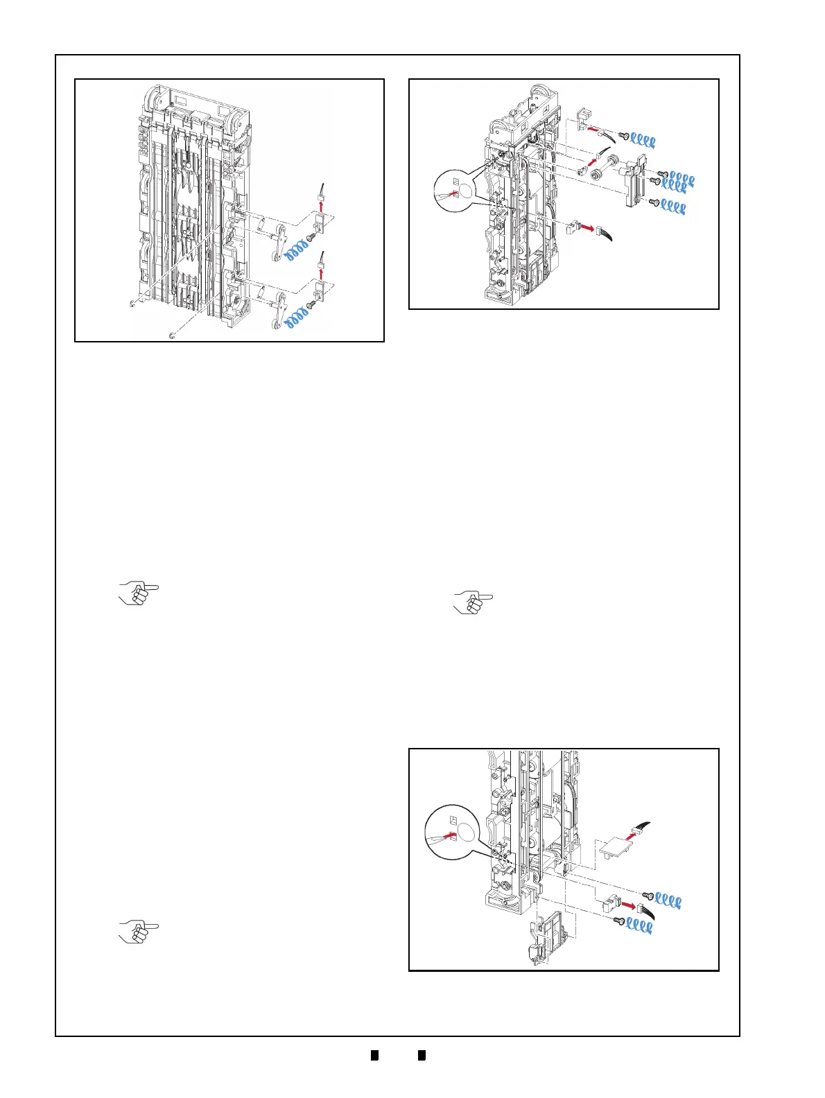
Banknote Transaction Sensor/
Transport Unit Encoder Board &
Double Note Sensor PT Removal
To remove the Banknote Transaction Sensor, the
Transport Unit Encoder Circuit Board, and the
Double Note Sensor PT, proceed as follows:
1. Remove the Banknote Transaction Sensor (Figure
4-17 a) from
the Rear Transport Assembly, and
unplug the single (1) Signal Connector (Figure 4-
17 b)
from the Sensor.
2. Remove the three (3) Mounting Screws (Figure 4-
17 d
1
, d
2
& d
3
) retaining the Upper Rear Trans-
port Cover (Figure 4-17 e) in plac
e, and take the
Upper Rear Transport Cover up and off the Rear
T
ransport Assembly.
3. Remove the single (1) Mounting Screw (Figure 4-
17 f) retaining
the Transport Unit Encoder Board
(Figure 4-17 g) in
place, and take the Transport
Unit Encoder Circuit Board off the Rear Trans-
port Assembly; then unplug the single (1) Signal
Connector (Figure 4-17 h).
4. Remove the Double Note Sensor PT (Figure 4-17
i)
from the Rear Transport Assembly, and then
unplug the single (1) Connector (Figure 4-17 j)
from the Double Note Sensor PT.
Banknote Transaction Sensor &
Box Sensor Board Removal
To remove the Banknote Transaction Sensor and
the Box Sensor Circuit Board, proceed as follows:
1. Remove the two (2) Mounting Screws (Figure 4-
18 a
1
& a
2
) retaining the Lower Rear Transport
Cover (Figure 4-18 b) in place
from the Rear
Transport Assembly.
2. Remove the Banknote Transaction Sensor (Figure
4-18 c) from the Rear T
ransport Assembly and
unplug the single (1) Signal Connector (Figure 4-
18 d) from the
Board.
3. Remove the Cash Box Det
ection Circuit Board
(Figure 4-18 f) from
the Rear Transport Assembly
and unplug the single (1) Signal Connector (Fig-
ure 4-18 g)
from the Board.
Figure 4-16 Flapper Open/Close Circuit Board
Removals
a
1
a
2
b
1
b
2
c
e
1
e
2
f
1
f
2
g
1
g
2
d
1
d
2
Figure 4-16 Flapper Open/Close Circuit
Board Removals
NOTE: If the Sensor does not
remove easily, place the head of a
small Flat-blade Screwdriver into the
hole located on the back side of the
Frame Transport Guide, and push
the Sensor out (Figure 4-17 c).
NOTE: If the Sensor does not
remove easily, place the head of a
small Flat-blade Screwdriver into the
hole located on the back side of the
Frame Transport Guide, and push
the Sensor out (Figure 4-17 c).
Figure 4-17 Banknote Transaction Sensor/
Transport Unit Encoder Circuit Board & Double
Note Sensor Removal
Figure 4-17 Banknote Transaction Sensor/
Transport Unit Encoder Circuit Board
& Double Note Sensor Removal
NOTE: If the Sensor does not
remove easily, place the head of a
small Flat-blade Screwdriver into the
hole located on the back side of the
Frame Transport Guide, and push
the Sensor out (Figure 4-18 e).
Figure 4-18 Banknote Transaction Sensor &
Box Detection Circuit Board Removal
Figure 4-18 Banknote Transaction Sensor & Box
Detection Circuit Board Removal