P/N 960-000164R_Rev. 3 {EDP #213631} © 2018, JAPAN CASH MACHINE CO., LTD.
Section 6 iPRO-RC™ Series Banknote Recycler Performance Tests
Individual Calibration and
Performance Test
This section explains the individual Calibration and
Performance Testing Procedures for each Sensor
within an iPRO-RC™ Unit. (Review “Sensor Cali-
bration and Performance Testing” on page 6-5 of
this Section for complete DIP Switch Settings).
Sensor Test Screen
Individual calibration and testing is available when
the “
iPRO-RC Maintenance Tool” is in the Sensor
Test Mode. To change the Mode, proceed as
follows:
1. Click on the “iPRO-RC Maintenance Tool” Tool
Bar’s “
Mode” pull-down Menu, and select “Sen-
sor Test
” from the selections available (Figure 6-
48 a).
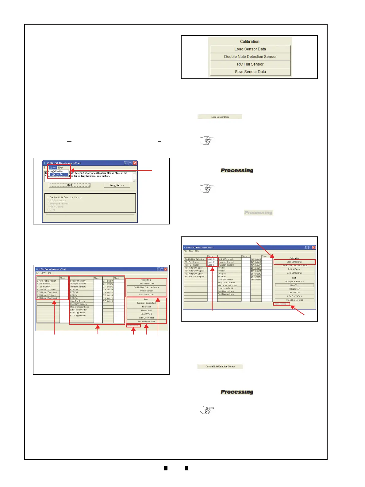
2. The Test Function Screen shown in Figure 6-49
will appear. Confirm that the
each Screen Button
Function and its related Status Cell indication
contains a result.
Individual Calibration
The following four (4) Function Buttons are used to
perform these related Calibrations:
• Load Sensor Data
• Double Note Detection Sensor
• RC Full Sensor
• Save Sensor Data
L
OAD
S
ENSOR
D
ATA
1. Click on the “Load Sensor Data”
Function Screen Button (Fig-
ure 6-51 a) to read
the current iPRO-RC™ Sensor
Data.
2. Confirm that the iPRO-RC™ Unit’s LED indi-
cates a steady Green Color
. The Bold Text “Pro-
cessing
” word appears during the
Test’s performance (Figure 6-51 b).
3. When reading current data
is complete, the Bold
Text “
Processing” word will turn to
Grayed-out text (Figure 6-51 b), and a “Load OK”
text message will appear in the related Status
resul
t Field (Figure 6-51 c).
D
OUBLE
N
OTE
D
ETECTION
S
ENSOR
C
ALIBRATION
1. Insert a piece of KS-087 Reference Paper into the
iPRO™ Transport Unit Insertion Slot.
2. Click on the “
Double Note Detection Sensor”
Calibration Screen Button
(Figure 6-52 a).
3. Confirm that the iPRO-RC™ Unit’s LED indi-
cates a steady Green Color
. The Bold Text “Pro-
cessing
” word will re-appear
during Performance Testing (Figure 6-52 b).
4. When Double Note Detect
ion Sensor Calibration
is complete, the KS-087 Reference Paper will be
returned, and the Bold Text “
Processing”
Figure 6-48 Sensor Test Selection
Figure 6-48 Sensor Test Selection
Figure 6-49 Test Function Listing Screen
Figure 6-49 Test Function Listing Screen
a) Calibration Result Indication Field
b) Performance Test Result Indication Field
c) “Processing” Indication
d) Performance Test Function Buttons
e) Calibration Function Buttons
Figure 6-50 Calibration Test Function Screen
Buttons
Figure 6-50 Calibration Test Function Screen
Buttons
NOTE: Always read the Sensor Data first
prior to starting one of the two (2) Sensor
Calibration Procedures.
NOTE: The LED will flash at a Green
Color Rate when an abnormal condition
occurs!
Figure 6-51 Load Sensor Data
Figure 6-51 Load Sensor Data
NOTE: The LED will flash at a Green
Color Rate when an abnormal condition
occurs!