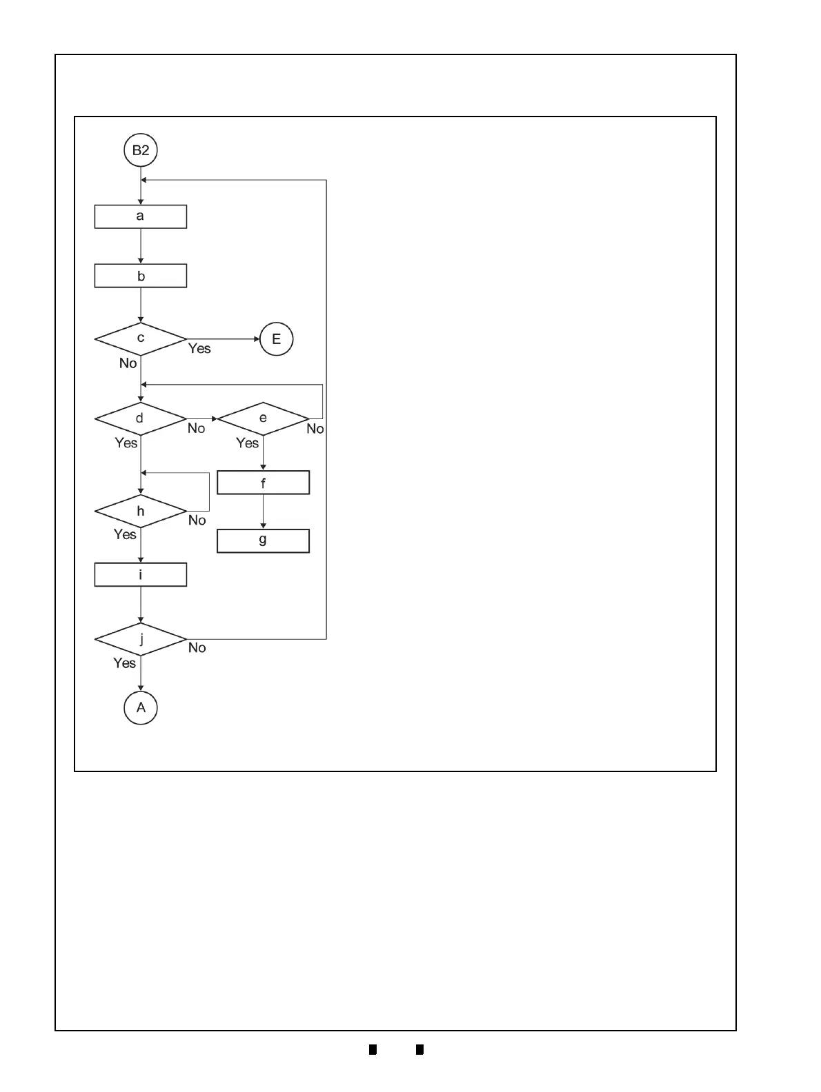
Figure 2-20 depicts a typical iPRO-RC™ Dispensing flow process.
B2) Return from the Figure 2-16 “Primary
Sequence” Flow on page2-18 of this Service
Manual
b) Sampling the Banknote data
c) Abnormal Error occur?
e) Was transportation retried ten (10) times?
f) Stop performance and sending Dispensing VEND
Signal (*5)
h) Is the dispensing Banknote removed?
a) Transporting the Banknote
E) To the Figure 2-21 “Abnormal Error” Flow on
page2-23 of this Service Manual
j) Has the number of required Banknote dispensed?
A) Return to Figure 2-16 “Primary Sequence” Flow
on page2-18 of this Service Manual
d) Is the Banknote transporting to the Insertion Slot?
g) Sending Abnormal Signal
i) Sending Dispensing VEND Signal
*5). The specific Banknote position may be treated as Abnormal, and an “Abnormal Condition Error” state will occur instead of
the normal dispensing “VEND Signal” being sent.