P/N 960-000164R_Rev. 3 {EDP #213631} © 2018, JAPAN CASH MACHINE CO., LTD.
Disassembly/Reassembly iPRO-RC™ Series Banknote Recycler Section 4
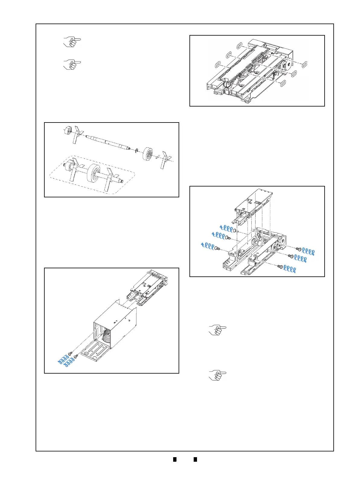
O-Ring (Pusher Plate) Removal
To remove the O-Rings on the Pusher Plate,
proceed as follows:
1. Remove the two (2) Mounting Screws (Figure 4-
35 a
1
& a
2
) retaining the Pusher Mechanism (Fig-
ure 4-35 b) in place, and slide
the Pusher Mecha-
nism out of the Cash Box Frame Housing.
2. Remove the six (6) O-Rings (Figure 4-36 a
1
to a
6
)
while lifting up on the Pusher Plate (Figure 4-36
b).
Roller Timing Belt
and O-Ring Removal
To remove the Timing Belt and O-Rings on the
Roller part of the Pusher Plate, proceed as follows:
1. Remove the six (6) Mounting Screws (Figure 4-
37 a
1
to a
6
) retaining the Pusher Plate (Figure 4-
37 b),
and take the Pusher Plate off the Pusher
Mechanism.
2. Remove the five (5) E-Rings (Figure 4-38 a
1
to
a
5
), the two (2) Gears (Figure 4-38 b
1
& b
2
) and
three (3) Bushings (Figure 4-38 c
1
, c
2
& c
3
) from
the Pusher Mechanism Assembly.
3. Remove the three (3) Frame Mounting Screws
(Figure 4-38 e
1
, e
2
& e
3
) from the Pusher Mecha-
nism Frame.
NOTE: Position the Impeller on the
slotted portion of the Shaft when re-
installing (Figure 4-34 g
1
& g
2
).
NOTE: Be sure that the Impeller
wing’s direction is tilted toward the
front, and that both sides of the
wings are set in a parallel position as
shown in the Figure 4-34 re-
assembly illustration. If the wings
are re-assembled in the wrong
direction, it can cause transportation
problems such as a Banknote Jam.
Figure 4-34 Impeller & Stop Roller Removal
Figure 4-34 Impeller & Stop Roller Removal
Figure 4-35 Pusher Mechanism Removal
Figure 4-35 Pusher Mechanism Removal
Figure 4-36 O-Ring Removals
Figure 4-36 O-Ring Removals
Figure 4-37 Pusher Plate Removal
Figure 4-37 Pusher Plate Removal
NOTE: Be careful that the Parallel
Pin (Figure 4-38 d) is not lost while
removing the Gears.
NOTE: One of the Screws is a
Phillips Self Tightening/Tapping type
(Figure 4-38 e
1
). Do not confuse its
placement with the others during re-
assembly.