P/N 960-000164R_Rev. 3 {EDP #213631} © 2018, JAPAN CASH MACHINE CO., LTD.
Section 4 iPRO-RC™ Series Banknote Recycler Disassembly/Reassembly
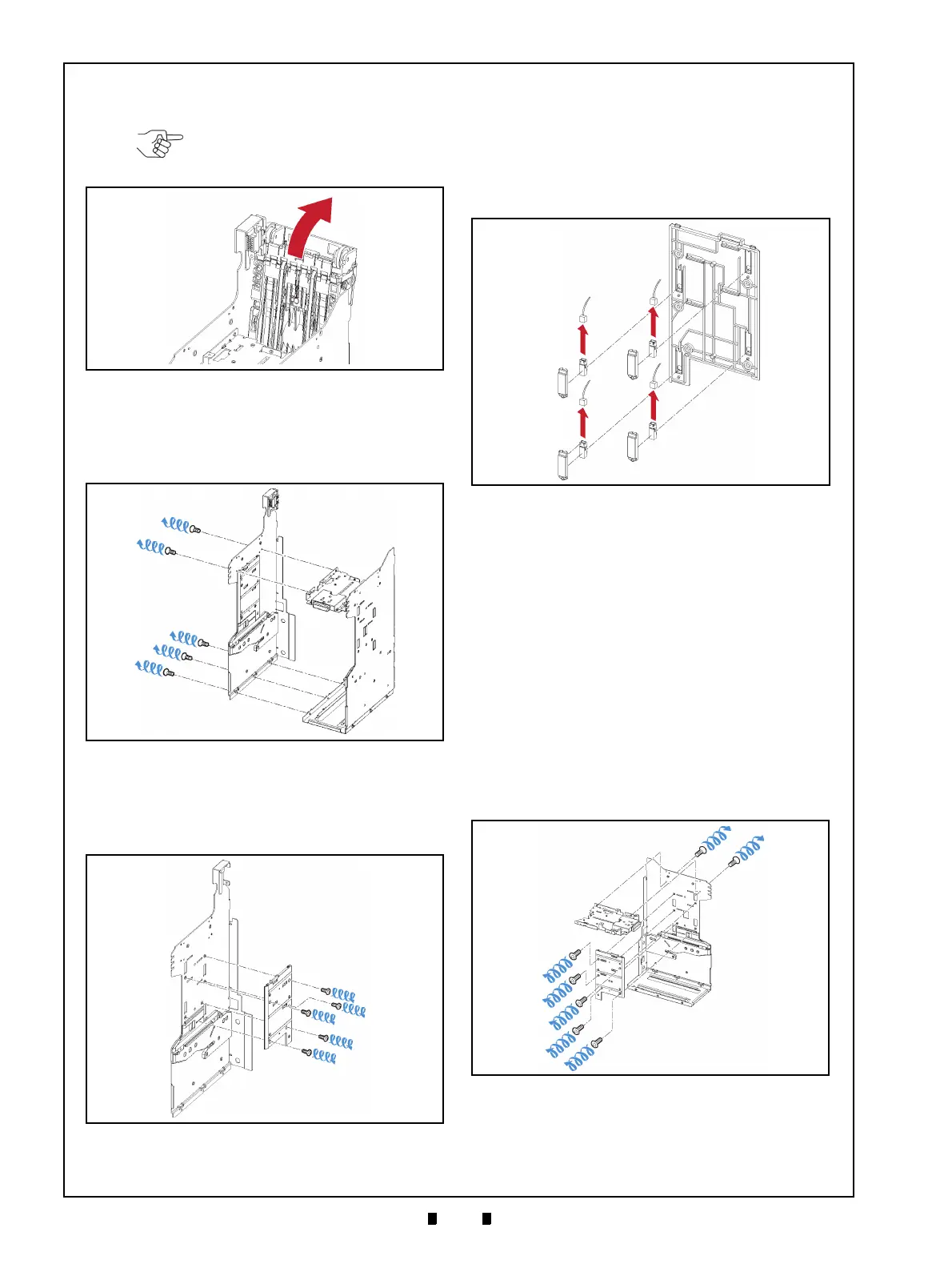
3. Tilt the Rear Transport Assembly (Figure 4-9 a)
backward and out of the Frame.
4. Remove the five (5) Mounting Screws (Figure 4-
10 a
1
to a
5
) retaining the Left Frame Plate in place
(Figure 4-10 b), and separate
the Left Plate from
the Frame bottom.
5. Remove the five (5) Mounting Screws (Figure 4-
11 a
1
to a
5
) retaining Frame Guide 4 in place (Fig-
ure 4-11 b), and
remove Frame Guide 4 from the
Left Frame Plate (Figure 4-11 c).
6. Remove the four (4) Sensor Covers (Figure 4-12
a
1
to a
4
); the Upper & Lower Full Sensor PTs
(Figure 4-12 b & c)
and the Upper & Lower End
Sensor LEDs (Figure 4-12 d & e) located
on the
left side of the Frame from Frame Guide 4, and
th
en unplug the four (4) related Signal Connec-
tors (Figure 4-12 f
1
to f
4
) from each Sensor.
Upper & Lower Full Sensor LED/
Upper & Lower End Sensor PT/
Lifter Home Position Sensor LED
& PT Removal
To remove the Upper & Lower Full Sensor LED,
the Upper & Lower End Sensor PT, and the Lifter
Motor Home Position Sensor LED & PT, proceed
as follows:
1. Remove the two (2) Mounting Screws (Figure 4-
13 a
1
& a
2
) retaining the UBA/iPRO-RC Internal
Top Frame (Figure 4-13 b)
in place, and take the
UBA/iPRO-RC Internal T
op Frame off of the
Right Frame Assembly (Figure 4-13 c).
2. Remove the five (5) Mounting Screws (Figure 4-
13 d
1
to d
5
) retaining Frame Guide 3 (Figure 4-13
NOTE: Be careful that the Harness
is not pinched between the Rear
Transport Assembly and the Frame!
Figure 4-9 Rear Transport Assy Removal
Figure 4-9 Rear Transport Assy Removal
Figure 4-10 Left Frame Plate Removal
Figure 4-10 Left Frame Plate Removal
Figure 4-11 Frame Guide 4 Removal
Figure 4-11 Frame Guide 4 Removal
Figure 4-12 Full Sensor PTs and End Sensor
LEDs Removal
Figure 4-12 Full Sensor PTs and End Sensor
LEDs Removal
Figure 4-13 Frame Guide 3 Removal
Figure 4-13 Frame Guide 3 Removal