P/N 960-000164R_Rev. 3 {EDP #213631} © 2018, JAPAN CASH MACHINE CO., LTD.
Disassembly/Reassembly iPRO-RC™ Series Banknote Recycler Section 4
e) in place, and separate the Frame Guide 3 from
the Right Frame.
3. Remove the six (6) Sensor Covers (Figure 4-14 a
1
to a
6
) and remove the Upper & Lower Full Sensor
LEDs (Figure 4-14 b & c),
the Upper & Lower
End Sensor PTs (Figure 4-14 d & e)
and the Lifter
Home Position Sensor LED (Figure 4-14 f) and
the Lifter Home Position Sensor PT (Figure 4-14
g) located
on Frame Guide 3; then unplug the six
(6) related Signal Connectors (Figure 4-14 h
1
to
h
6
) from each Sensor.
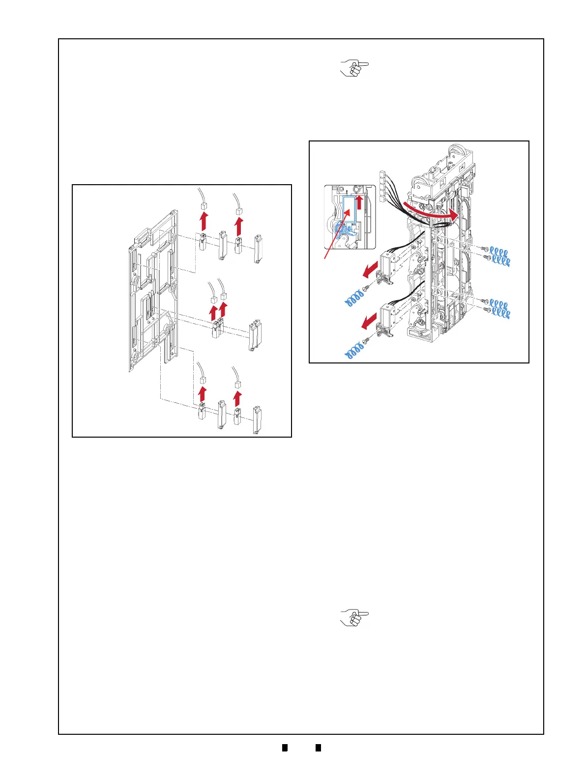
Upper & Lower Flapper Pusher
Lever Solenoid Removal
To remove the Flapper Pusher Lever Solenoid,
proceed as follows:
1. Pull the Harness (Figure 4-15 a) to the back side
of the Rear Transport Assembly (Figure 4-15 b).
2. Remove the six (6) Mounting Screws (Figure 4-
15 c
1
to c
6
) retaining the Upper Flapper Pusher
Lever Solenoid (Figure 4-15 d)
and the Lower
Flapper Pusher Lever Solenoid in place (Figure 4-
15 e);
then remove both the Upper and Lower
Flapper Lever Solenoids from the Rear Transport
Assemb
ly.
Flapper Open/Close Circuit Board
Removal
To remove the Flapper Open/Close Circuit Board,
proceed as follows:
1. Remove the two (2) E-Rings (Figure 4-16 a
1
&
a
2
) retaining the two (2) Flapper Pusher Brackets
(Figure 4-16 b
1
& b
2
) in place, and remove the
Flapper Pusher Brackets from the Rear T
ransport
Assembly (Figure 4-16 c).
2. Remove the two (2) Mounting Screws (Figure 4-
16 e
1
& e
2
) retaining the Flapper Open/Close Cir-
cuit Boards (Figure 4-16 f
1
& f
2
) in place, and
unplug each of their related Signal Connectors
(Figure 4-16 g
1
& g
2
); then remove the two (2)
Flapper Open/Close Circuit Boards from the Rear
T
ransport Assembly.
Figure 4-14 Full Sensor LEDs, End Sensor PTs
and Lifter Home Position Sensor LED/PT
Removal
a
1
a
2
a
3
a
4
a
5
a
6
b
c
d
e
f
g
h
1
h
2
h
3
h
4
h
5
h
6
Figure 4-14 Full Sensor LEDs, End Sensor PTs
and Lifter Home Position Sensor
LED/PT Removal
NOTE: When re-assembling both
the Upper and Lower Flapper
Solenoids, pull upward in the
direction of the Red Arrow indicated
in the Figure 4-15f inset, and then
replace their related carrier with their
mounting screws.
Figure 4-15 Upper & Lower Flapper Pusher
Lever Solenoid Removal
Figure 4-15 Upper & Lower Flapper Pusher
Lever Solenoid Removal
NOTE: Before removing the Flapper
Pusher Brackets, remove the two (2)
Springs (Figure 4-16 d
1
& d
2
) from
the Rear Transport Assy.