P/N 960-000164R_Rev. 3 {EDP #213631} © 2018, JAPAN CASH MACHINE CO., LTD.
iPRO-RC™ Series
Banknote Recycler
Section 2
This section provides installation and operating
instructions for the iPRO-RC™ Series Banknote
Recycler Unit (iPRO-100-SH2-RC; iPRO-RC™).
The information within contains the
following features:
• Installation Procedure
• Cable Interconnection
• DIP Switch Configuration
• Switch Configuration
• Connector Pin Assignments
• Preventive Maintenance
• Clearing a Banknote Jam
• Cleaning Procedure
• Standard Interface Circuit Schematics
• Operational Flowchart
Installation Procedure
Holes are provided in each Frame Unit to accom-
modate mounting the iPRO-RC™ during installa-
tion. Select and perform the following steps
required to install the iPRO-RC™ Unit:
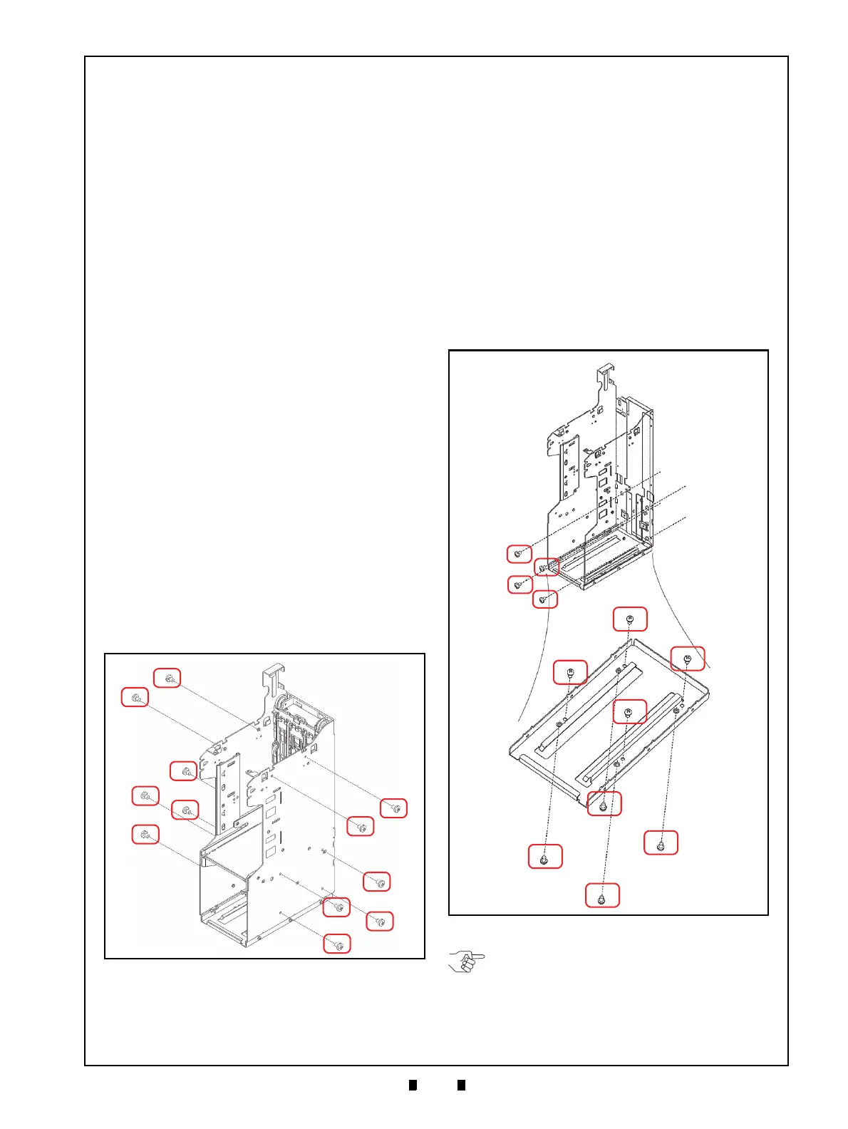
1. When a side mounting configuration is preferred,
bolt the left or right side of the iPRO-RC™ Frame
into its intended location using six (6) M4 Screws
from either side of the Frame (Figure 2-1).
2. When a rear mounting configu
ration is preferred,
bolt the inside back of the iPRO-RC
™ Frame into
its intended location using four (4) M4 Phillips
Head Screws (Figure 2-2 a
1
through a
4
).
3. When a bottom mounting configuration is pre-
ferred, bolt the inside or outside of the
iPRO-RC
™ Frame into its intended location
using four (4) M4 Phillips Head Screws. To bolt
the Frame down from the inside, place the screws
in the four un-threaded holes located inside the
Frame (Figure 2-2 b
1
to b
4
); or bolt the Frame
down from the outside using th
e four (4) threaded
Stud Insert holes located on the outside of the
Frame (Figure 2-2 c
1
to c
4
).
Figure 2-1 M4 Screws Locations (Right/Left)
Figure 2-1 M4 Screws Locations (Right/Left)
Figure 2-2 M4 Screws Locations (Rear &
Bottom)
Figure 2-2 M4 Screws Locations (Rear & Bottom)
NOTE: Choose two (2) of the five (5)
installation configuration sides shown, and
bolt the correct number of M4 Screws firmly
in place. When bolting the Screws from the
outside, the maximum length of each M4
Screw must be less than 7mm long.