P/N 960-000164R_Rev. 3 {EDP #213631} © 2018, JAPAN CASH MACHINE CO., LTD.
Disassembly/Reassembly iPRO-RC™ Series Banknote Recycler Section 4
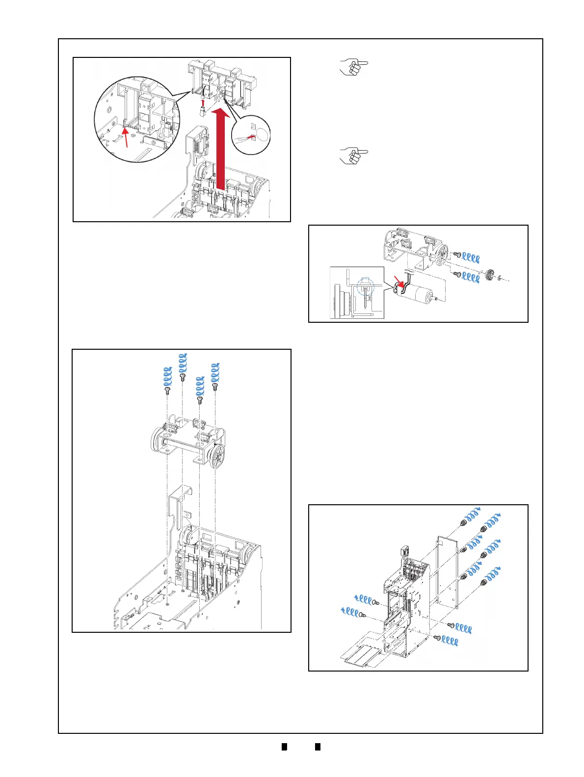
Lifter Motor Assy Removal
To remove the Lifter Motor Assembly, proceed as
follows:
1. Remove the four (4) Mounting Screws (Figure 4-
6 a
1
to a
4
) retaining the Lifter Motor Bracket in
place (Figure 4-6 b), and tak
e the Lifter Motor
Bracket off of the Frame.
2. Remove the single (1) E-Ring (Figure 4-7 a) and
the single (1) Gear (Figure 4-7 b) fr
om the
Assembly.
3. Remove the two (2) Mounting Screws (Figure 4-7
d
1
& d
2
) retaining the Lifter Motor Assembly in
place (Figure 4-7 e)
, and remove the Lifter Motor
Assembly from the Lift Motor Bracket.
Upper & Lower Full Sensor PT/
Upper & Lower End Sensor
LED Removal
To remove the Upper/Lower Full Sensor PT (Photo
Transistor) and the Upper/Lower End Sensor LED,
proceed as follows:
1. Remove the six (6) Mounting Screws (Figure 4-8
a
1
to a
6
) retaining the Rear Frame Cover (Figure
4-8 b) to
the back side of the Frame.
2. Remove the four (4) Mounting Screws (Figure 4-
8 c
1
to c
4
) retaining the Center Shelf in place
(Figure 4-8 d)
and slide it out of the Frame.
Figure 4-5 Emission Side Double Note Sensor
Removal
Figure 4-5 Emission Side Double Note
Sensor Removal
Figure 4-6 Lifter Motor Bracket Removal
Figure 4-6 Lifter Motor Bracket Removal
NOTE: Ensure that the Parallel Pin
(Figure 4-7 c) does not fall out when
removing the Gear.
NOTE: When re-assembling the
Motor, ensure that the Harness is
correctly positioned as shown in
Figure 4-7f, and that the Encoder
Gear (Figure 4-7 g) does not touch
either wall of the Sensor (Figure 4-7
h).
Figure 4-7 Lifter Motor Assy Removal
Figure 4-7 Lifter Motor Assy Removal
Figure 4-8 Rear Frame & Middle Frame
Removal
Figure 4-8 Rear Frame & Middle Frame Removal