Table 58: Esmated Values for Factors Causing Link Loss
(Connued)
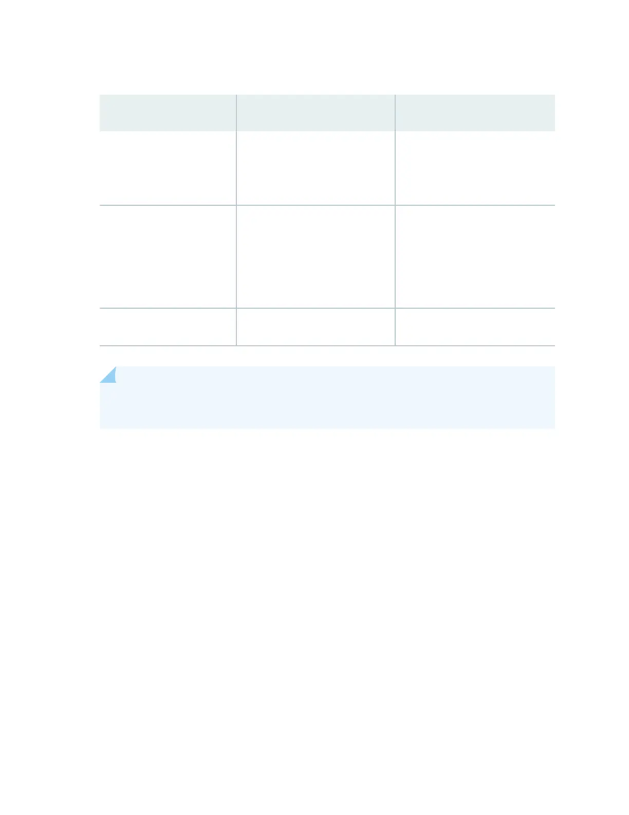
Link-Loss Factor Esmated Link-Loss Value Sample (LL) Calculaon Values
Splice 0.5 dBm This example assumes 2 splices. Loss
for two splices:
(2) * (0.5 dBm) = 1 dBm
Fiber aenuaon
• Mulmode—1 dBm/km
• Single mode—0.5 dBm/km
This example assumes the link is 2
km long. Fiber aenuaon for 2 km:
• (2 km) * (1.0 dBm/km) = 2 dBm
• (2 km) * (0.5 dBm/km) = 1 dBm
Clock Recovery Module (CRM) 1 dBm 1 dBm
NOTE: For informaon about the actual amount of signal loss caused by equipment and other
factors, see your vendor documentaon for that equipment.
2. Calculate the (
P
M
) by subtracng (
LL
) from (
P
B
):
P
B
– LL = P
M
(13 dBm) – (0.5 dBm [HOL]) – ((5) * (0.5 dBm)) – ((2) * (0.5 dBm)) – ((2 km) * (1.0 dBm/km)) – (1 dB
[CRM]) = P
M
13 dBm – 0.5 dBm – 2.5 dBm – 1 dBm – 2 dBm – 1 dBm = P
M
P
M
= 6 dBm
The calculated power margin is greater than zero, indicang that the link has sucient power for
transmission. Also, the power margin value does not exceed the maximum receiver input power.
Refer to the specicaon for your receiver to nd the maximum receiver input power.
150