5—
QSFP+ ports
12—
USB port
6—
Fan module in slot 1
13—
Console port
7—
AC power supply in slot 0
NOTE: DC power supplies are installed in the power supply slots in models that use DC power.
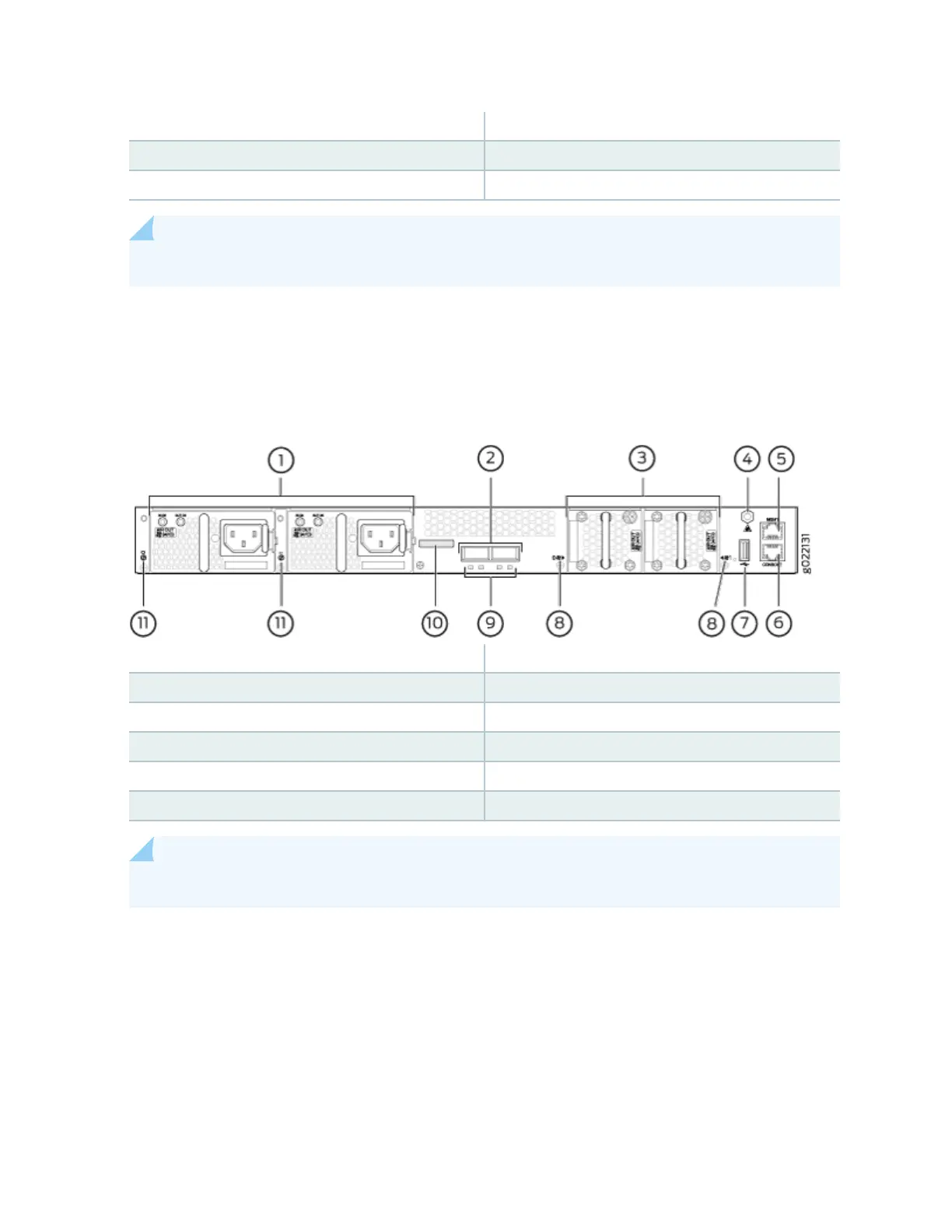
Figure 14 on page 28 shows the components on the rear panel of a 32-port EX4300 switch (with two
AC power supplies and two fan modules installed).
Figure 14: Components on the Rear Panel of a 32-Port EX4300 Switch
1—
AC power supplies in slot 0 and slot 1
7—
USB port
2—
QSFP+ ports
8—
Fan module slot numbers and LEDs
3—
Fan modules in slot 0 and slot 1
9—
QSFP+ port LEDs
4—
ESD point
10—
Serial number label
5—
Management port
11—
Power supply slot numbers
6—
Console port
NOTE: DC power supplies are installed in the power supply slots in models that use DC power.
28