Table 17: Uplink Modules Used in EX4300-48MP and EX4300-48MP-S Switches
(Connued)
Uplink Module Name Model Number Figure
4-port 1-Gigabit
Ethernet SFP/
10-Gigabit Ethernet SFP
+ uplink module
EX-UM-4SFPP-MR
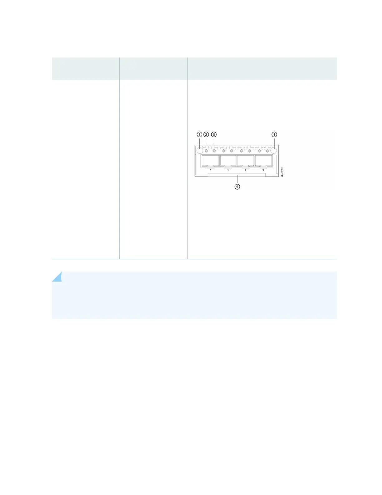
Figure 25: LEDs on the 4-Port 1-Gigabit Ethernet
SFP/10-Gigabit Ethernet SFP+ Uplink Module
1. Capve screws of the uplink module
2. Link acvity LED of the uplink module port
3. Status LED of the uplink module port
4. Handle of the uplink module
NOTE: When you install an uplink module in the switch or replace an uplink module with another
uplink module, the switch detects the ports on the uplink module. The switch creates the
required interfaces when transceivers are installed in these ports.
The SFP+ uplink module ports in EX4300 switches can operate either in 10-gigabit or in 1-gigabit mode
depending on the transceiver you install in them. The operang mode for an SFP+ uplink module is
shown in the output of the show chassis pic fpc-slot
slot number
pic-slot
slot number
command.
Each port on the uplink modules has a pair of LEDs that indicate the link acvity and status of the port.
See "Network Port, Built-In QSFP+ Port, Uplink Port, and Uplink Module Port LEDs on EX4300
Switches" on page 74 for details about the status and link acvity LEDs.
SFP+ uplink modules are shipped with dust covers installed in the ports. QSFP+ uplink module is
shipped with a dust cover installed in one of the ports.
68