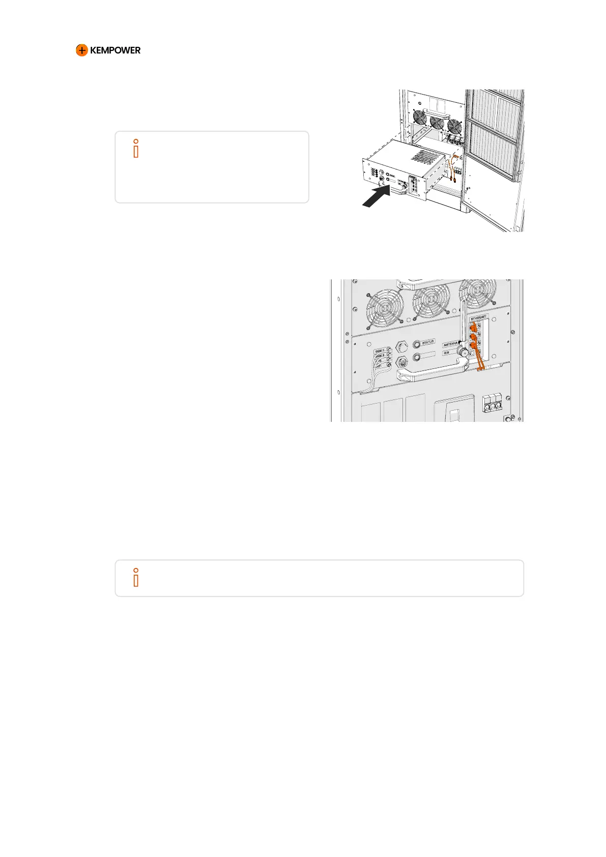
5. Install the control module back
in the charging power unit.
NOTE
Route the cables through
the openings between the
mains module and the control
module.
6. Connect the extension Ethernet
cable from the Ethernet terminal
block on the DIN rail to any port
of the Ethernet switch in the
front face of the control module.
5.2.11.2. Satellite
1. Terminate the Ethernet cable wires with the RJ45 connectors.
•
The connector wiring scheme is standard T-568B.
NOTE
The Ethernet cable is not included in the delivery.
CHARGING EQUIPMENT FOR ELECTRIC VEHICLES INSTALLATION MANUAL
CONFIDENTIAL – CERTIFIED PARTNERS 97 REV 2.40 EN 04-2024