Configuring the DIP Switch
The configuration of the DIP switch is important for making a system in a Multi RF Deck/ Multi Control Head structure behave
properly.
KRK-14H (Remote Kit for Head), KRK-15B (Remote Kit for RF Deck), and KCH-20R (Featured Panel) are equipped
with the DIP switch. The DIP switch is the switch for managing the order of RF Decks and Control Heads connected in the
system and for determining the terminal of CAN (Controller Area Network) communication. The purpose of each switch is
as follows:
Table 16-1 DIP Switch
DIP Switch
KCH-20R/ KRK-14H
(Control Head Side)
KRK-15B
(RF Deck Side)
SW1 Not used For the terminal of CAN communication
SW2 Not used Not used
SW3 Not used
For the numbering of RF Decks
SW4 For the numbering of Control Heads
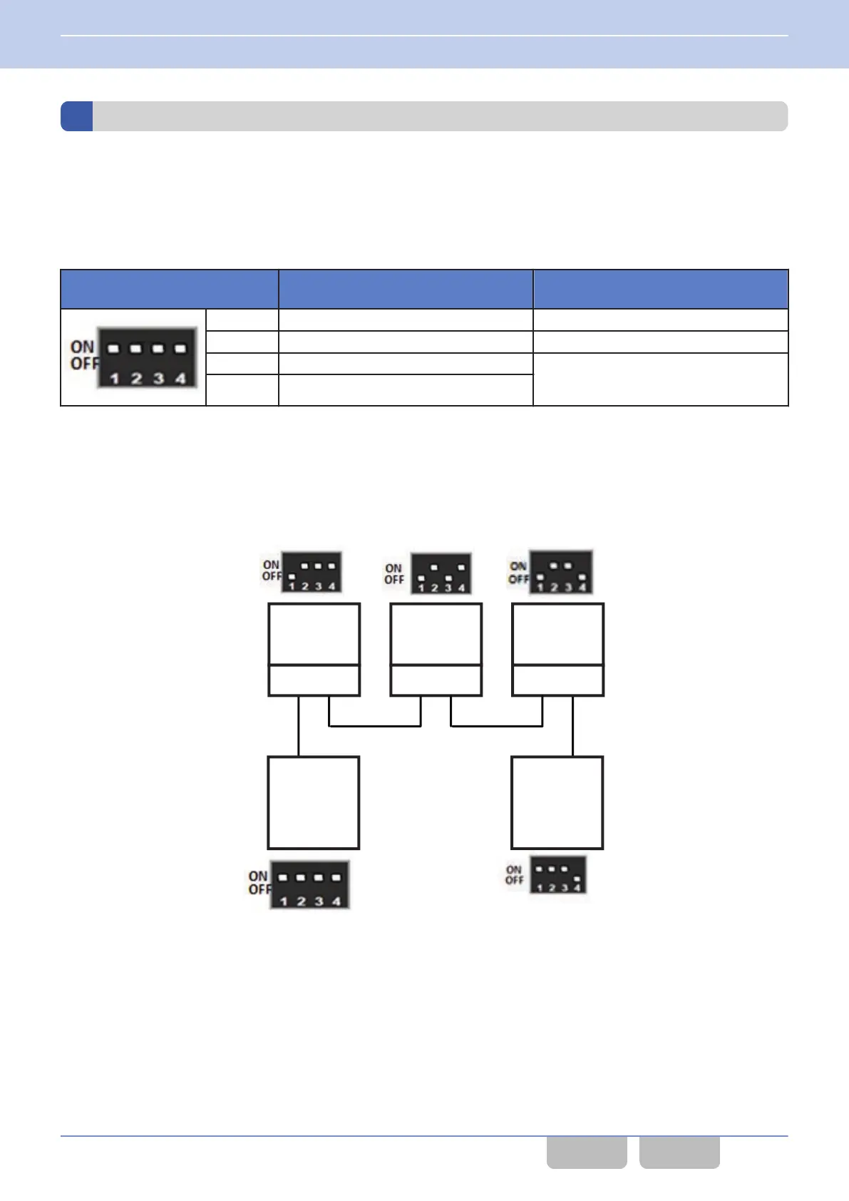
The numbering of RF Decks and Control Heads by using the DIP switch is important to structuring Multi RF Deck/ Multi
Control
Head. If the RF Decks and Control Heads are not numbered correctly, the system may not start up properly. Number
the RF Decks and Control Heads based on the following conditions, and correctly configure the DIP switch.
0
The Control Head to be connected to RF Deck 1 is Control Head 1.
0
The Control Head to be connected to RF Deck 3 is Control Head 2.
0
No Control Head is connected to RF Deck 2.
RF Deck
1
Control Head
1
RF Deck
2
RF Deck
3
Control Head
2
KRK-15B KRK-15B KRK-15B
Figure 16-15 DIP Switch Configuration
16 MULTI RF DECK/ MULTI CONTROL HEAD
16.4 Configuring the Initial Configuration
Common FUNC (K, F)/Ver 2.20 258
CONTENTS INDEX
 Loading...