17.13
About the Pin Arrangement for KCT-72 and the Connection of
External Devices
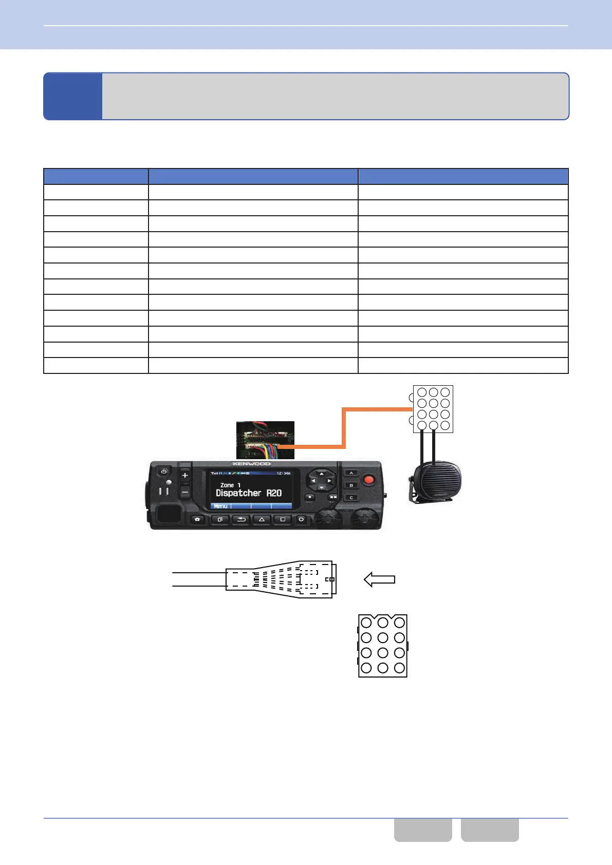
The following is the pin arrangement for KCT-72:
Table 17-2 Pin Arrangement for KCT-72
Pin No. Color Name
1 RED IGN
2 Black SB
3 LIGHT GREEN GND
4 LIGHT BLUE AUX_MIC
5 YELLOW AUX_ME
6 GRAY Ai1
7 WHITE Ai2
8 PURPLE Ao1
9 PINK Ao2
10 ORANGE SP-
11 BROWN SP+
12 DARK GREEN GND
KCT-72
KES-5
1 2 3
4 5 6
7 8 9
10 11 12
Figure 17-89 KCH-20R with KCT-72
A
(MOLEX)
VIEW A
(Partial enlargement)
1 2 3
4 5 6
7 8 9
10 11 12
Figure 17-90 KCT-72 (Connection Cable)
17 STRUCTURING A MULTI RF DECK/ MULTI CONTROL HEAD
17.13 About the Pin Arrangement for KCT-72 and the Connection of External Devices
Common FUNC (K, F)/Ver 2.20 387
CONTENTS INDEX
 Loading...