Connecting the RF Deck by Using a D-sub 25-pin Cable
Caution
Connect a D-sub 25-pin cable to the transceiver after confirming that the FPU data for Mobile Relay Station is
written. A D-sub 25-pin cable may malfunction if the D-sub 25-pin cable is connected to the transceiver with the
FPU data for Mobile Relay Station not written to the transceiver.
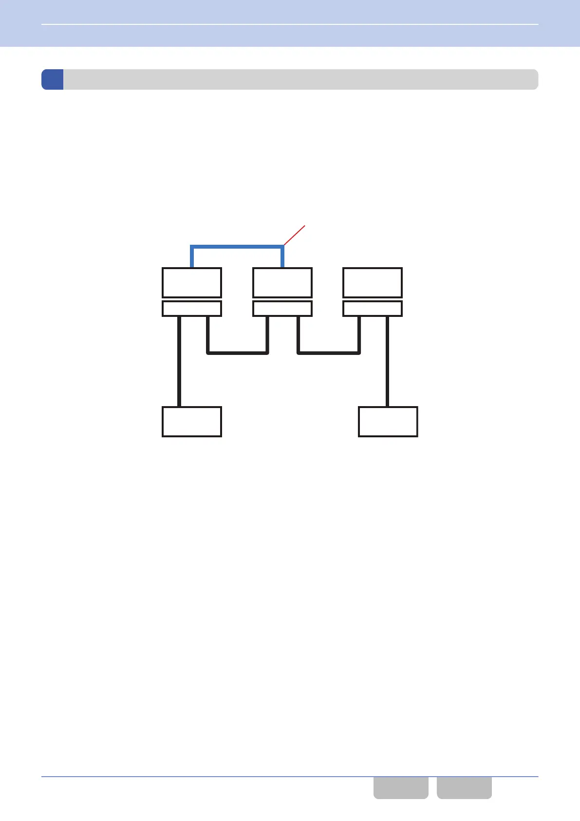
To
use the Mobile Relay Station function, 2 RF Decks need to be connected by a D-sub 25-pin cable, and a Control Head
needs to be connected to one of the RF Decks.
The following diagram is an example of RF Deck 1 and RF Deck 2 configured as Mobile Relay Channels in a Triple RF Deck
structure:
2
Control Head
RF Deck 3
KRK-15B
RF Deck 2
KRK-15B
1
Control Head
RF Deck 1
KRK-15B
D-sub 25 pin cable
Figure 16-86 Connection Diagram
RF Deck 1 and RF Deck 2 can be connected by COM port 1 or COM port 2.
In analog communications, RF Decks are compatible with COM port 2. Also, in digital communications, RF Decks are
compatible with COM port 1 and COM port 2.
16 MULTI RF DECK/ MULTI CONTROL HEAD
16.18 Relaying the Received Signal (Mobile Relay Station)
Common FUNC (K, F)/Ver 2.20 327
CONTENTS INDEX
 Loading...