3
Configure
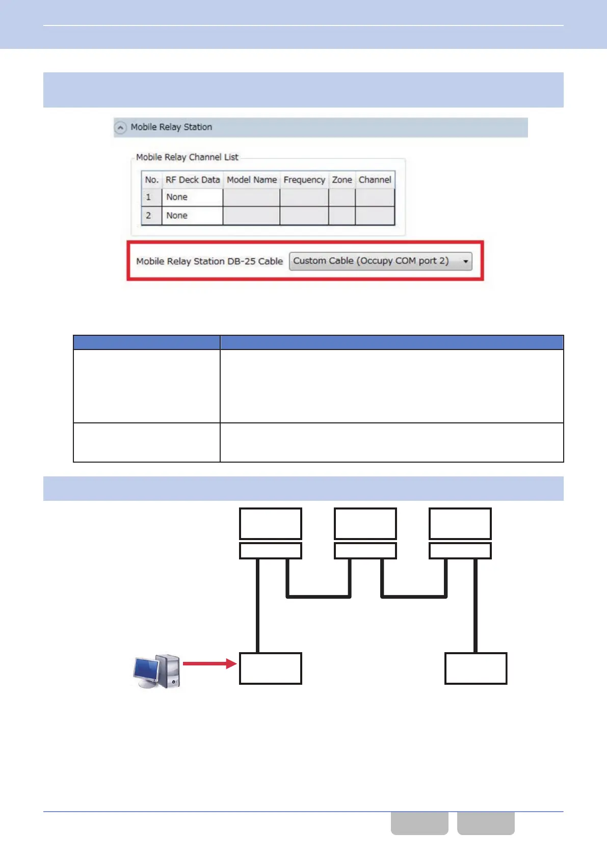
the communication port to be used in Mobile Relay Station Mode in Mobile Relay Station DB-25
Cable.
Figure 16-84 Mobile Relay Station DB-25 Cable
Table 16-18 Mobile Relay Station DB-25 Cable
Configuration Description
Cross Cable (Occupy COM port 1)
This is the configuration for using a commercially available Null Modem cable.
However, if a commercially available cable is used, an analog channel cannot
be used as a Mobile Relay Channel. Also, the configuration cannot be used
depending on the cable. Use a Null Modem cable of the same wiring as the wiring
diagram in “R COM port 1” of “Connecting the RF Deck by Using a D-sub 25-
pin Cable”.
Custom Cable (Occupy COM
port 2)
This is the configuration for using a self-made cable.
Any of an analog channel, an NXDN channel, and a P25 channel can be used
as a Mobile Relay Channel.
4
Write the FPU data.
2
Control Head
RF Deck 3
KRK-15B
RF Deck 2
KRK-15B
1
Control Head
RF Deck 1
KRK-15B
KPG-D1/ D1N
Figure 16-85 Triple RF Deck/ Dual Control Head (FPU Setting)
16 MULTI RF DECK/ MULTI CONTROL HEAD
16.18 Relaying the Received Signal (Mobile Relay Station)
Common FUNC (K, F)/Ver 2.20 326
CONTENTS INDEX
 Loading...