Keysight B2980B User’s Guide, Edition 1 69
Installation
Installing the Interlock Circuit
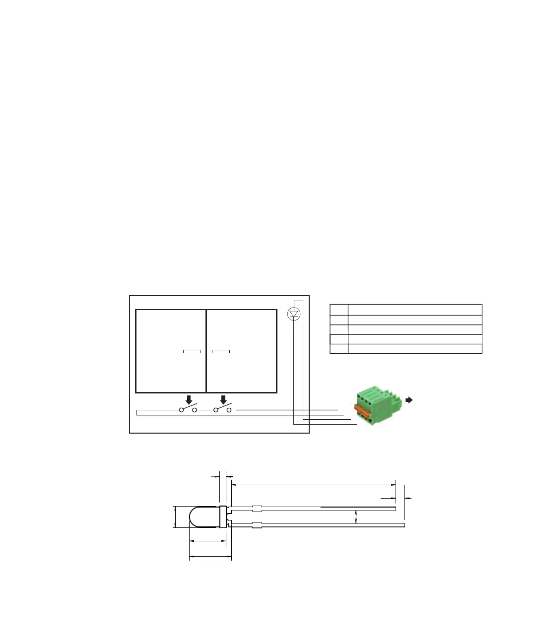
The LED is used as a high voltage indicator which is lit when the
B2985B/B2987B is in the high voltage output status over 21 V.
3. Use a wire and connect the two switches in series between the pins 1 and 2 of
the Interlock connector head.
To connect the wire to the Interlock connector head, just insert the wire into
the appropriate wire hole.
If you inserted the wire into a wrong hole, remove it and retry. You can remove
the wire by pushing the associated button (orange) and pulling the wire.
4. Use a wire and connect the LED between the pins 3 and 4 of the Interlock
connector head.
5. Connect the Interlock connector head to the Interlock connector on the
B2985B/B2987B rear panel.
Figure 2-2 Interlock Circuit
Figure 2-3 Dimensions of the LED (Keysight part number 1990-0486)
Mechanical switches
Shielding box
LED
Access door
Interlock circuit
connected to
B2985B/B2987B
Interlock connector
Interlock connector head, 4-pin plug
Pin
1
2
3
4
Signal
Ground
Interlock
10 mA at 2 V in High voltage status
Ground
1
2
3
4
Cathode (-)
24
Units: mm
1.3
0.8
3.2
4.5
5.9
Anode (+)
2.5
 Loading...


