Modify your X and Y Offset values in the window shown at the end of Section 11.03.3. Start with 1 mm
adjustments (like shown above). Remember to switch the Units to mm and then write down the numbers
you’re entering onto the next printout.
Repeat the test and note whether you need to increase or decrease X and/or Y. Again, adjust by 1 mm
unless you now need to do the reverse. For example, let’s say you adjusted X from 0.0 to 1.0 after the first
test. After the second test, do this:
If X still needs to be increased, then make X = 2.0 for the third test
However, if X now needs to be decreased, them make X = 0.5 for the third test
After adjusting by 0.5 mm, you will want to adjust by 0.2 mm. Continue narrowing in on the correct
calibrations. Once you are adjusting by 0.1 mm, you should be able to achieve the optimum settings. If you
are still off by “just a hair” in one direction or the other, then adjust by a final 0.05 mm.
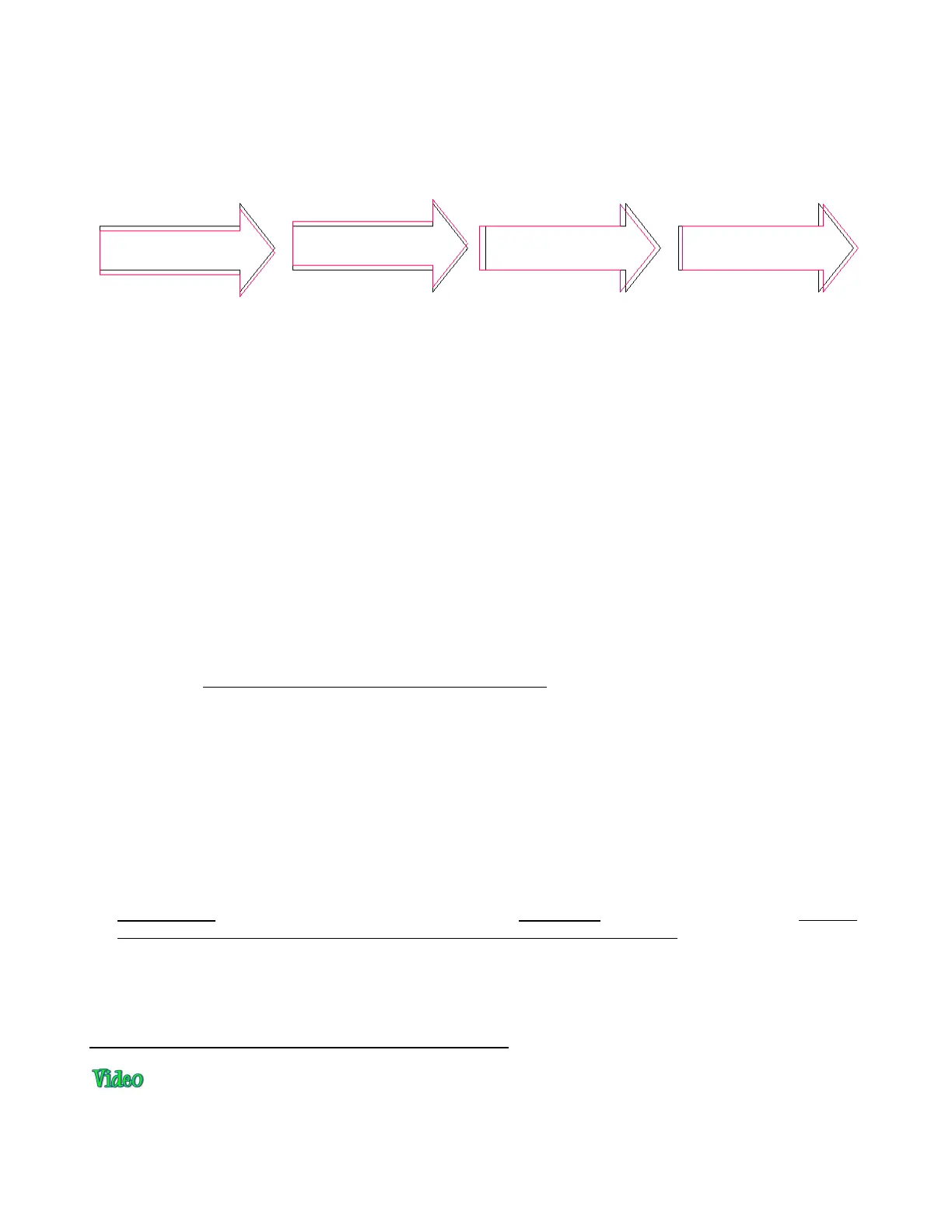
During the testing, you may find that one side is aligned but the other is not. For example, the cut line may
be perfectly aligned with the print line on the lower side of the arrow but a little above the arrow along the
upper side. Adjust the calibration based on the side that is off. It won’t cause the other side of the arrow to
be off.
If you find that one or two arrows are perfect but the others are off:
Check the Cut Speed setting. Too high of a speed can cause inaccuracies.
Make sure the pinch wheels are still centered under the white rectangles.
Make sure the bottom of the mat, the pinch wheels, and the grit shafts are clean.
Make sure nothing is interfering with the smooth traveling of the mat.
Make sure the blade isn’t cutting too deeply into the mat. Lessen the blade exposure by retracting it a
tiny bit back into blade holder.
IMPORTANT! Once you have your calibration completed, write down these final X and Y offsets! Some of
the software updates can cause the calibration numbers to reset to default values. It will save you time and
frustration to have these numbers recorded so that you can quickly reenter them without repeating the
calibration process.
11.04 Preparing an Actual Print and Cut Application
Here are the typical steps when preparing a PNC application:
Prepare the image that will be printed which can be either or both of the following:
o An imported raster image such as a JPG or PNG which will need tracing (refer to Section 7.03)
 Loading...