110 Kollmorgen - December 2011
MMC Smart Drive Hardware Manual - 230V 1/3 PHASE MMC SMART DRIVE
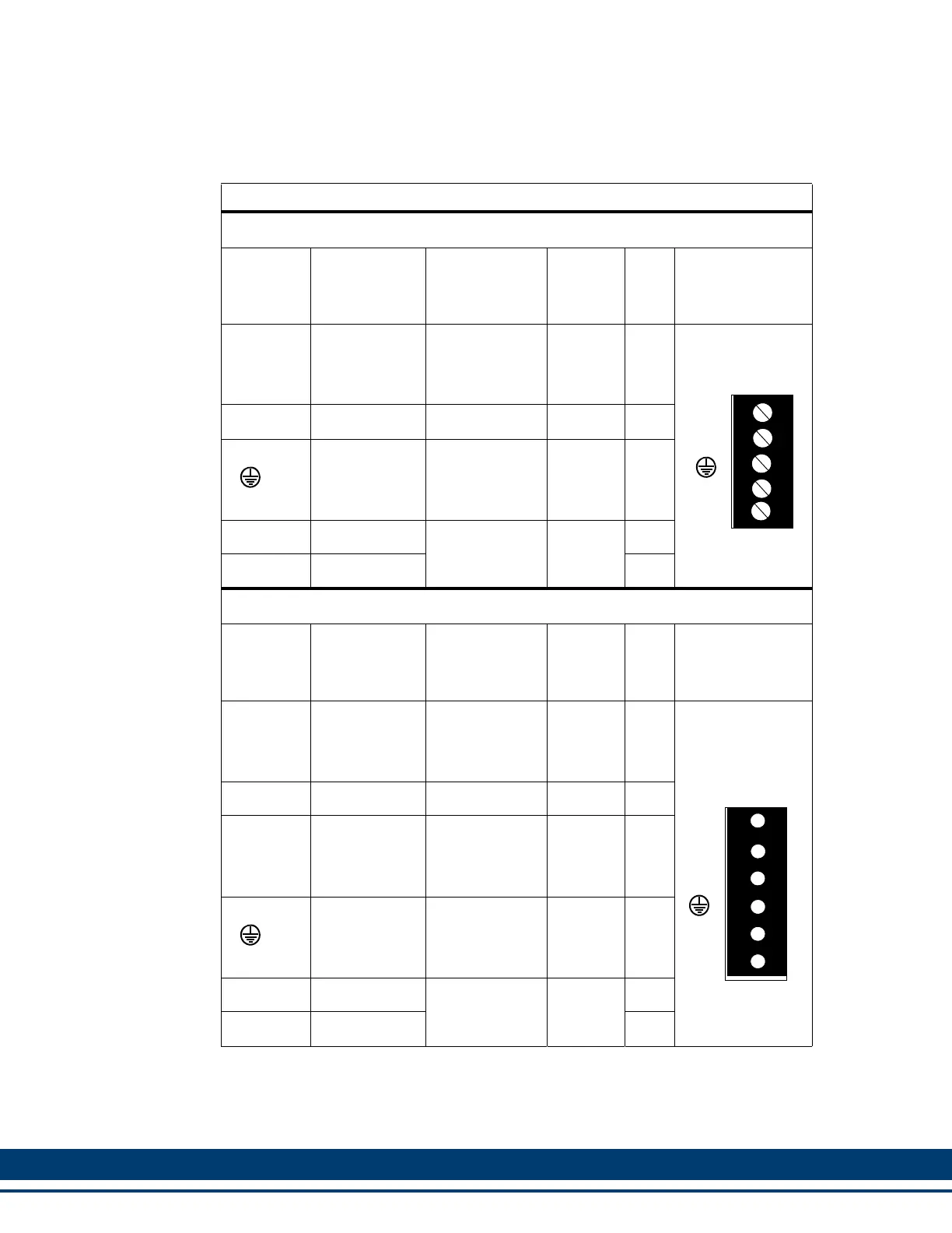
5.2.1 24 VDC IN/Brake Connector
Table 5-35: Pin Assignment for 24 VDC IN/Brake Connector
Single Phase Drive
Terminal
Label
Signal Type
Signal
Description
PiCPro
I/O
Label
In/
Out
Connector
Pinout
+24V Logic Power
+24V user
supplied pow-
er signal termi-
nal.
N/A In
5-pin Plugable
Screw Terminal
COM Common +24V Common N/A In
Protective
Ground
Must be con-
nected to Pro-
tective Earth
Ground (SPG)
N/A In
BR+ Brake Relay +
Refer to Figure
Figure 5-7.
Output5
/Relay
Out
BR- Brake Relay - Out
Three Phase Drive
Terminal
Label
Signal Type
Signal
Description
PiCPro
I/O
Label
In/
Out
Connector
Pinout
+24V Logic Power
+24V user
supplied pow-
er signal termi-
nal.
N/A In
6-pin Plugable
Cage Clamp
Terminal
COM Common +24V Common N/A In
EN Drive Enable
Safe-off Sig-
nal. (See sec-
tion 5.2.1.1 on
page 111).
N/A In
Protective
Ground
Must be con-
nected to Pro-
tective Earth
Ground (SPG)
N/A In
BR+ Brake Relay +
Refer to Figure
Figure 5-7.
Output5
/Relay
Out
BR- Brake Relay - Out
+24V
COM
BR+
BR-
+24V
COM
BR+
BR-
EN
 Loading...