116 Kollmorgen - December 2011
MMC Smart Drive Hardware Manual - 230V 1/3 PHASE MMC SMART DRIVE
5.3 Specifications - 230V MMC Smart Drive
5.3.1 General Data for all 230V Models
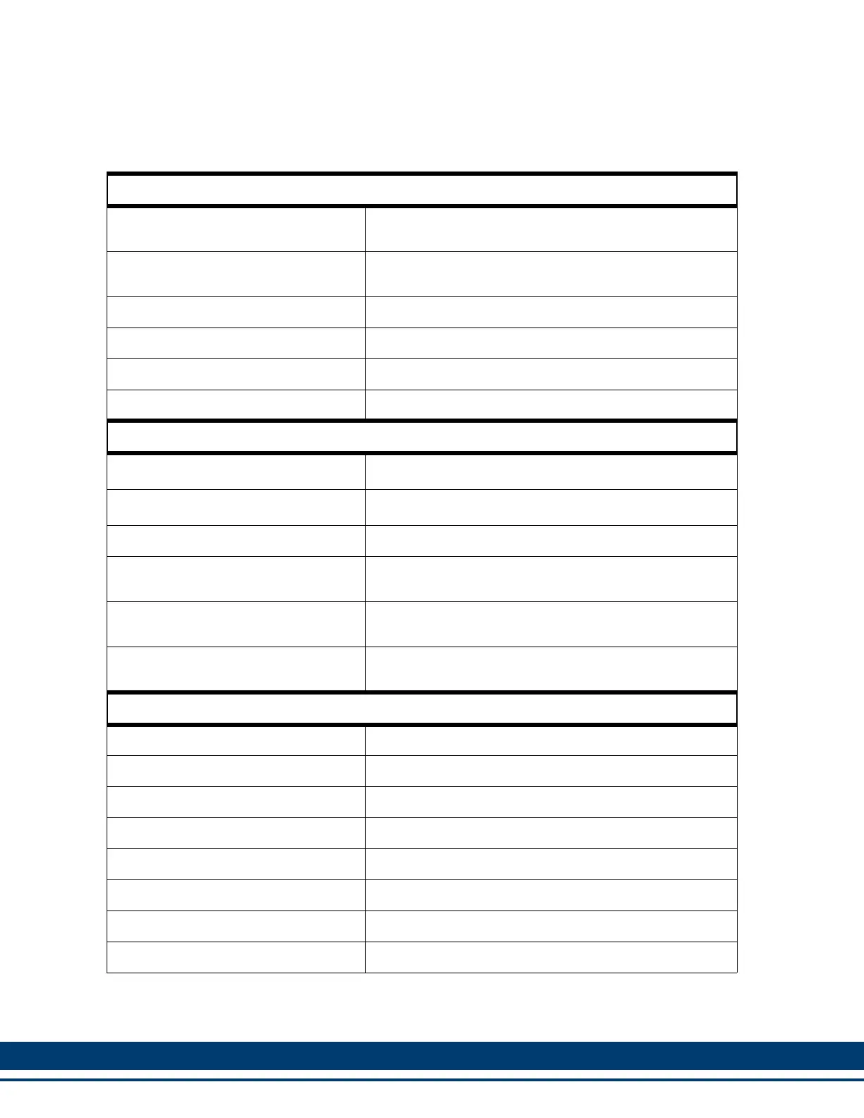
General Drive Data
Minimum wire size for input power and
motor wires
1.5mm2 (16 AWG) 75° C copper.
Maximum tightening torque for power
wire terminals
1.17 Nm (10.4 in-lbs.)
Commutation Three Phase Sinusoidal
Current Regulator Digital PI 125 µsec. update rate
Velocity Regulator Digital PID - 250 µsec. update rate
Environmental Data
Operating Temperature Range
7
o
C to 55
o
C (45
o
F to 131
o
F)
Storage Temperature Range
-30
o
C to 70
o
C (-22
o
F to 158
o
F)
Humidity 5% to 95% non-condensing
Altitude
1500 m (5000 ft)
Derate 3% for each 300 m above 1500m
Vibration Limits (per IEC 68-2-6)
Operating/Non-operating
10-57 Hz (constant amplitude.15 mm)
57 - 2000 Hz (acceleration 2 g)
Shock (per IEC 68-2-27)
Non-operating
Four shocks per axis (15g/11 msec)
F1 and F2 Feedback Inputs
Input receiver type Maxim 3098 A quad B differential RS422 receiver
Encoder signals Differential quadrature
Input threshold ±200 mV
Input termination 150Ω, provided internally
Maximum input voltage 5V peak to peak differential -10 to +13.2V common mode
Maximum input signal frequency 720 K Hz (2.88 M feedback counts per second)
+5V regulated output 500ma max between F1 and F2
+9V regulated output 150ma max between F1 and F2

 Loading...