102 Kollmorgen - December 2011
MMC Smart Drive Hardware Manual - 230V 1/3 PHASE MMC SMART DRIVE
5.1.7 Drive I/O Connector (IO)
The 26-pin HD female D-sub Drive I/O Port connector (labeled “IO” on the front of the
Drive) provides connection between various devices and the Drive. This port provides
one Analog Command Input, two differential Fast Inputs, several General Purpose I/O
points (wiring example shown in See Figure 5-6 on page 108), and buffered versions
of the feedback device connected to the F1 port.
• Pin descriptions are provided in Table 5-30
• Pin assignments are provided in Table 5-31
• Available MMC Control cables are described in Table 5-32
• The available Flying Lead cable is described in Table 5-33.
• Available Breakout Boxes and Cables are described in Table 5-34.
• Breakout Box dimensions are shown in Figure 5-4
• Breakout Board dimensions are shown in Figure 5-5
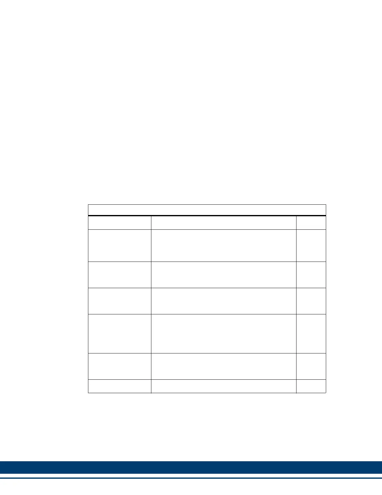
Table 5-30: Pin Description for Drive I/O Connector (IO)
Signal Type Notes Pins
Analog Command
Inputs (Analog In-
terfaced MMC-SD
only)
Analog velocity or torque commands of 0 to +/-
10V. Separate scale and offset parameters are
used relative to the command signal being velocity
or torque
14, 15
Fast Inputs (Digital
Interfaced MMC-SD
only)
Used for latching encoder position.
8, 9, 11,
12
General Purpose
Software Assign-
able Inputs
24VDC sourcing type. Default assignments: Pin 17
(GPIN1) = Drive Enable, Pin 18 (GPIN2) = Fault
Reset
17, 18,
19, 20,
21, 22
Buffered F1 Encod-
er Output
RS485 drivers are used and the signal that is out-
put depends on the encoder or resolver type used.
See specifications in Chapter 5 of this manual.
These signals are generated after the feedback
from the F1connector is filtered and processed.
1, 2, 3,
4, 5, 6
General Purpose
Software Assign-
able Outputs
24VDC sourcing type. Default assignment:
Pin 26 (GPOUT4) = Drive Ready
23, 24,
25, 26
IO24V, IO24COM 24 VDC inputs for powering GPIN and GPOUT I/O. 10, 16
 Loading...