118 Kollmorgen - December 2011
MMC Smart Drive Hardware Manual - 230V 1/3 PHASE MMC SMART DRIVE
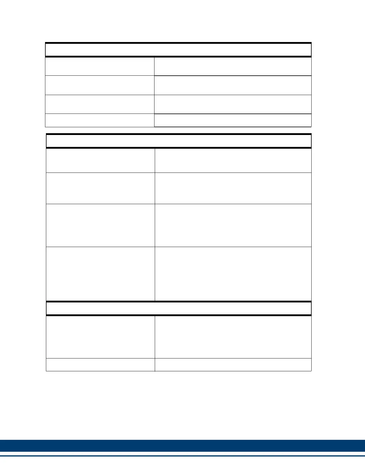
Digital Link In/Out Ports (Digital Interfaced MMC-SD only)
“In” port
Sends and receives high speed data to and from connect-
ed MMC-SD’s “Out” port.
“Out” port
Sends and receives high speed data to and from connect-
ed MMC-SD’s “In” port.
Cable Type
Shielded, Straight Pinned, CAT5 or better (CAT5e, CAT6,
etc.)
Maximum Cable Length 30 m (98.4 ft)
Drive I/O Connector Encoder Emulation Output
F1 Motor Feedback Type
Input Limit
Encoder Emulation Output
(A quad B Differential Output)
Incremental Encoder
720 KHz
2.88 M counts/sec.
The motor encoder A/B/I inputs are electrically buffered
and retransmitted via the Drive I/O connector.
High Resolution Encoder
100 KHz
400 K counts/sec.
The encoder SIN/COS signals are electrically squared
and retransmitted as A/B. The index mark “I” is synthe-
sized by the drive control DSP. Absolute position informa-
tion is not available via the Encoder Emulation Output.
Resolver
500 RPS
2.00 M counts/sec.
The field-installable resolver interface module converts
the motor resolver to 1024 lines/4096 counts per revolu-
tion of A/B encoder output. The module synthesizes the
index mark “I” once per revolution of the resolver. Abso-
lute position information is not available via the Encoder
Emulation Output.
Conformity
CE Marked (only for Single Phase
Drives. Three Phase Drives pending).
Conforms to Low Voltage Directive 73/23/EEC (amended
by 93/68/EEC) and EMC Directive 89/336/EEC (amend-
ed by 92/31/EEC and 93/68/EEC).
Conformance is in accordance with the following stan-
dards:
EN 50178 and EN61800-3
UL and C/UL Listed E233454
 Loading...