Kollmorgen - December 2011 229
MMC Smart Drive Hardware Manual - S200-DLS DRIVE
8.1.8 Drive I/O Port Details
There are four DC Inputs and four DC Outputs available for interfacing to various
devices. This section explains these Inputs/Outputs in detail.
Table 8-13: I/O Power Port Pin Descriptions
Function Notes Pin
I/O 24V Power Nominal 24 Vdc to power Drive I/O 3
I/O 24V Common I/O 24V common 2
DC Inputs 5 and 6
Sink/source
This pin determines whether Drive I/O inputs 5
& 6 are sourcing (this pin connected to 24 Vdc
Common) or sinking (this pin connected to 24
Vdc)
6
DC Inputs 7 and 8
Sink/source
This pin determines whether Drive I/O inputs 7
& 8 are sourcing (this pin connected to 24 Vdc
Common) or sinking (this pin connected to 24
Vdc)
5
Chassis Ground
This pin should be connected to Chassis
Ground
1
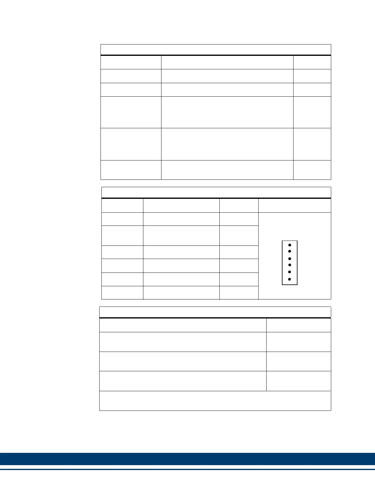
Table 8-14: I/O Power Port Pin Assignments
Pin Signal In/Out Connector Pinout
1 Chassis Ground In
6-Pin plugable Screw
Terminal Connector
2
Drive I/O 24 Vdc Com-
mon
In
3 Drive I/O 24 Vdc In
4 N/C N/A
5 Input 7&8 Sink/Source In
6 Input 5&6 Sink/Source In
Table 8-15: Drive I/O and I/O Power Port Accessories
Description Part Number
6-pin spring-contact pluggable mating connector for the I/O
Power Port (J6)
M.1302.7662
8-pin spring-contact pluggable mating for connector for the
Drive I/O Port (J7)
M.1302.7627
Kit containing one each of J6 and J7 connectors as de-
scribed above
M.3000.0728
See section 8.2 on page 231 for Connector Kits that include connectors for the Pow-
er Section connectors (J1, J2, J3, and J4)
6
1
J6
POWER
I/O
 Loading...