Kollmorgen - December 2011 133
MMC Smart Drive Hardware Manual - 460V 3 PHASE MMC SMART DRIVE NEXTGEN
6.1.4 Feedback Connectors (F1 & F2)
The two 15-pin female Feedback connectors (labeled “F1” and “F2” on the front of the
Drive) provide an interface between two feedback devices. A detailed description of
the capabilities and limitations of connected devices can be found in section 6.1.4.1
on page 138.
• Pin descriptions for the F1 connector are provided in Table 6-4
• Pin assignments for the F1 connector are provided in Table 6-5
• Pin descriptions for the F2 connector are provided in Table 6-6
• Pin assignments for the F2 connector are provided in Table 6-7
• The available Flying Lead cable is described in Table 6-9.
• Available Breakout Boxes and Cables are described in Table 6-10.
• Breakout Box dimensions are shown in Figure 6-2
• Breakout Board dimensions are shown in Figure 6-3
• Feedback Port to Motor Cables are described in section 6.1.4.2 on page 143
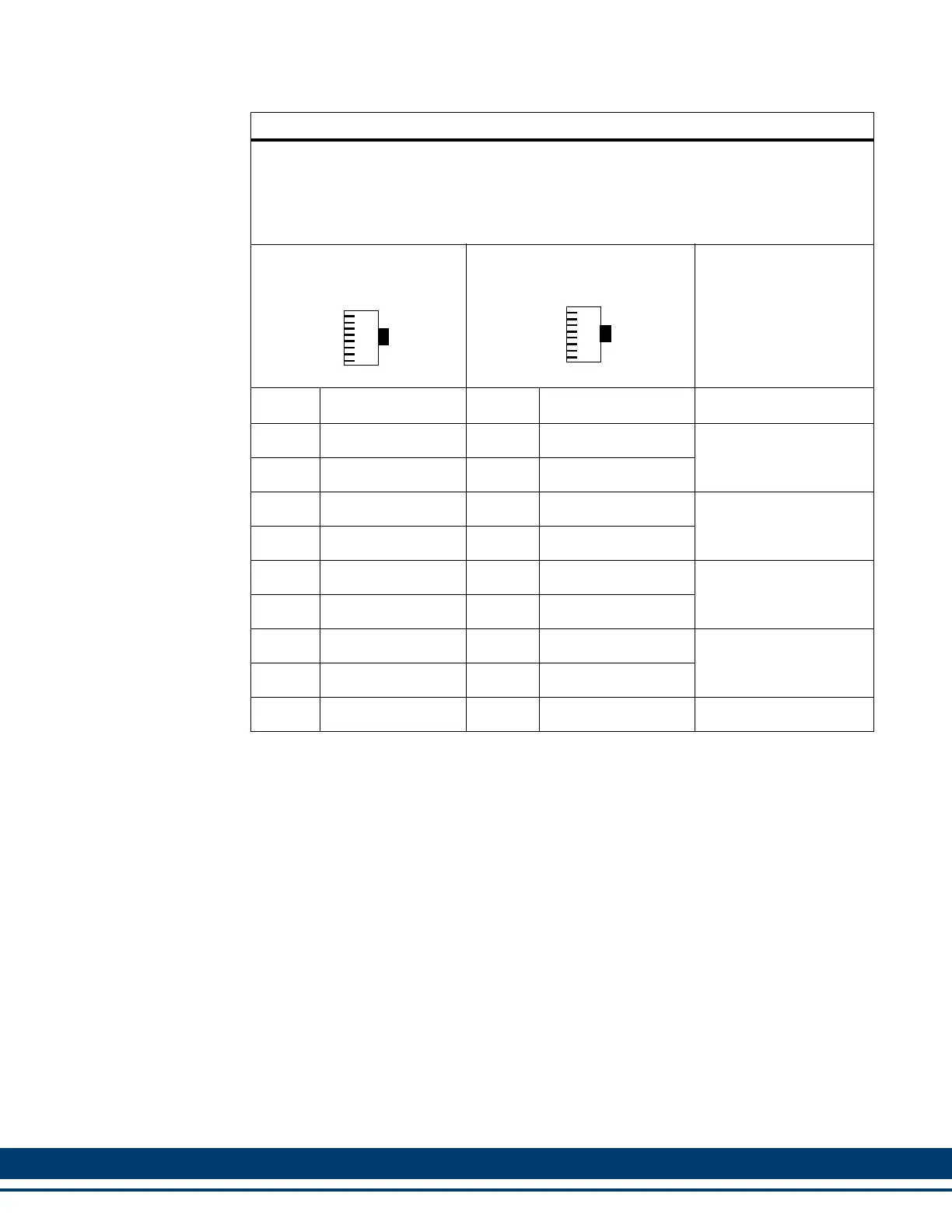
Table 6-3: Digital Link Port “IN” to “OUT” Cables
Part Numbers:
.3 M (1.0 ft): M.1302.8285 .6 M (2.0 ft): M.1302.8286 1 M (3.3 ft): M.1302.8287
2 M (6.6 ft): M.1302.8288 3 M (9.8 ft): M.1302.8289 5 M (16.4 ft): M.1302.8300
10 M (32.8 ft): M.1302.8301 15 M (49.2 ft): M.1302.8302 30 M (98.4 ft): M.1302.8303
Cable type: 28 AWG, shielded, twisted pair, 8 conductor.
8-Pin RJ-45 Plug (to Digital
Link Port “OUT”, face view)
8-Pin RJ-45 Plug (to Digital
Drive “IN”, face view)
Pin Signal Pin Signal Notes
1 Transmit Data + 1 Receive Data + Twisted
2 Transmit Data - 2 Receive Data - Pair
3 Receive Data + 3 Transmit Data + Twisted
6 Receive Data - 6 Transmit Data - Pair
4 None 4 None Twisted
5 None 5 None Pair
7 None 7 None Twisted
8 None 8 None Pair
Shell Drain Shell Drain
1
8
1
8
 Loading...