Kollmorgen - December 2011 137
MMC Smart Drive Hardware Manual - 460V 3 PHASE MMC SMART DRIVE NEXTGEN
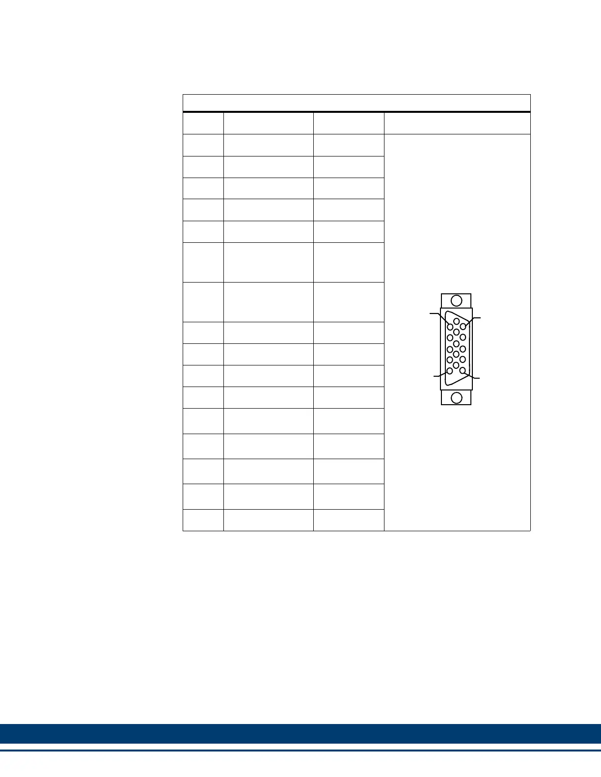
Table 6-7: Pin Assignments for Feedback Connector (F2)
Pin Signal Name In/Out Connector Pinout
1 S1 In
15-pin Female
HD D-Sub
2 S2 In
3 S3 In
4 N/U
5 N/U
6
I2 (Encoder)
Com+ (SFD
a
)
a. SFD will be offered in a future release of the Drive
In/Out
b
b. This pin is an Input when F2 is configured for Encoder Input, an Output
when F2 is configured for Encoder Output, and an Input/Output when F2 is
configured for SFD (future).
7
I2/ (Encoder)
Com- (SFD
a
)
In/Out
b
8 Temperature+ In
9 Temperature- N/A
10 +5V Out
11 0V Out
12 A2
In/Out
c
c. This pin is an Input when F2 is configured for Encoder Input, and an Output
when F2 is configured for Encoder Output.
13 A2/
In/Out
c
14 B2
In/Out
c
15 B2/
In/Out
c
Shell Shield In
5
1
15
11
 Loading...