154 Kollmorgen - December 2011
MMC Smart Drive Hardware Manual - 460V 3 PHASE MMC SMART DRIVE NEXTGEN
6.2.3 Motor/Brake Connector
The Motor/Brake Connector consists of a pluggable 6-pin screw-terminal block, and
provides connection to the motor and the motor brake that is being controlled by the
Drive.
Table 6-20: Recommended Fuses & Holders
For Drive Model
Combin-
ation
Fuse
Fuse Part
Number
Fuse
Holder
Type 3P
Fuse Holder
Part Number
MMC-SDN-1.8-460 DFJ6 M.3000.0190 30 Amp M.1016.1046
MMC-SDN-3.6-460 DFJ10 M.3000.1321 30 Amp M.1016.1046
MMC-SDN-7.2-460 DFJ15 M.3000.0191 30 Amp M.1016.1046
MMC-SDN-14.4-460 DFJ30 M.3000.0194 30 Amp M.1016.1046
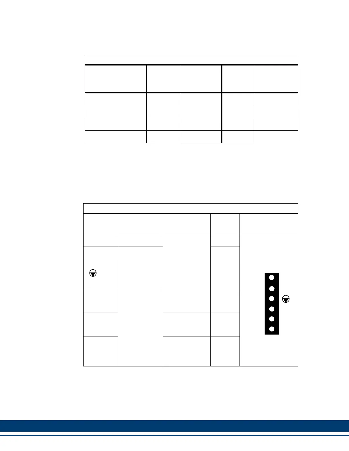
Table 6-21: Pin Assignment for Motor/Brake Connector
Terminal
Label
Signal Type
Signal
Description
In/Out Pin Sequence
-BR Brake Relay -
Motor brake
control
a
a. This output can be defined and used as a General Purpose Output in PiCPro
(Output3), but is typically defined as the Motor Brake Control.
In
6-pin Plugable
Screw Terminal
+BR Brake Relay + Output3
Protective
Ground
Must be con-
nected to Pro-
tective Earth
Ground (SPG).
In
U
Motor Power
Power U-phase
from the drive to
the motor.
Out
V
Power V-phase
from the drive to
the motor.
Out
W
Power W-
Phase from the
drive to the mo-
tor.
Out
U
V
-BR
+BR
W
M
O
T
O
R
 Loading...