Kollmorgen - December 2011 217
MMC Smart Drive Hardware Manual - S200-DLS DRIVE
8.1.5 Digital Link Ports
The two 8-pin RJ-45 Digital Link Port connectors (labeled “J10 DLINK IN” and “J9
DLINK OUT” on the front of the Drive) provide communications between the S200-
DLS and:
• another S200-DLS Drive
• a Digital Link Accessory (DL-DIU, Slice I/O Coupler, etc.)
• an MMC Smart Drive (including a Drive that contains a Drive Resident MMC Con-
trol)
• an MMC-DSA Control (MMC-DSA2, -DSA4, -DSA8, -DSA16)
• a Digital Standalone MMC Control (MMC-D32, -D64)
Also provided are two green “Link” lights located between the RJ-45 connectors. The
right light will be on if there is a Drive or Digital Control connected to the “IN” port, and
the left light will be on if there is a Drive connected to the “OUT” port.
A “straight-through” shielded cable must be used when connecting to another device.
Connect the cable from the Drive’s “DLINK OUT” port to the next Digital Link Device’s
“DLINK IN” port, or from the MMC Digital Control’s Digital Link port to the Drive’s
“DLINK IN” port. Refer to the Standalone MMC Hardware Manual for Standalone
Digital Control information.
• Pin descriptions for are provided in Table 8-2
• Pin assignments are provided in Table 8-3
• The available Digital Link Port to Digital Drive cables are described in Table 8-4
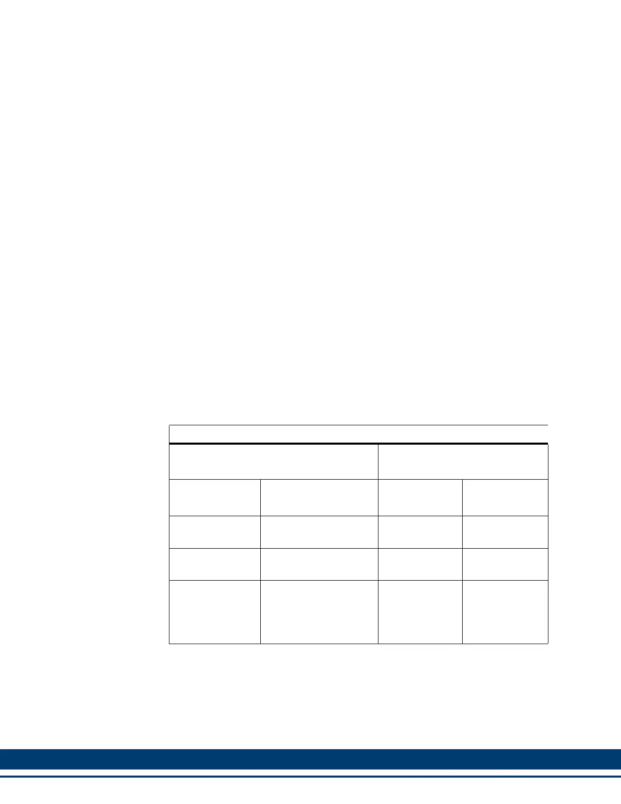
Table 8-2: Digital Link Port Pin Description
Digital Link Connector (IN/OUT)
Signals
Pin
Function Notes
“In”
Connector
“Out”
Connector
Receive Data+/-
Receives data from
connected drives.
1,2 3,6
Transmit Data +/-
Transmits data to con-
nected drives.
3,6 1,2
Protective
Ground
Shield connection. Pro-
vides a path for the
ground signal to an ex-
ternal single point
ground.
Connector Shell Connector Shell
 Loading...