266 Kollmorgen - December 2011
MMC Smart Drive Hardware Manual - DRIVE RESIDENT DIGITAL MMC CONTROL
drive until the 20-pin connector is completely seated and the Drive Resident Digi-
tal MMC Control is seated against the threaded standoffs installed in step 5.
10. Tighten the 5 screws loosened in step 7
11. Fasten the Drive Resident Digital MMC Control onto the threaded standoffs using
the lockwashers and screws removed in step 5.
12. Replace the control board unit back into the drive, and turn the locking screws ¼
turn counter-clockwise to secure the unit in place.
12.3 System Wiring Guidelines
The Drive Resident Digital MMC Control relies on electrical signals to report what is
going on in the application and to send commands to it. In addition, signals are
constantly being exchanged within the system. The Drive Resident Digital MMC
Control is designed for use in industrial environments, but some guidelines should be
followed.
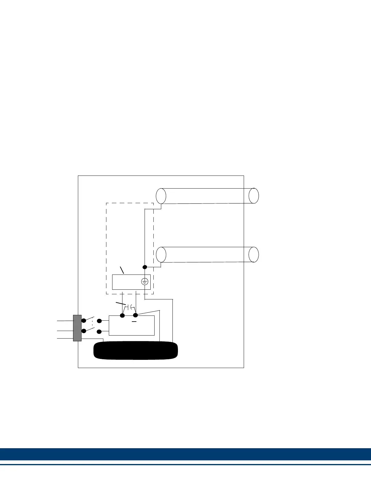
Figure 12-2: Recommended EMC Compliant Connections
Inside a control cabinet, connect the shields of shielded cables. The two different
methods of terminating shields are used to accommodate two different immunity
requirements. Immunity required inside an enclosure is considered lower because
cables are typically less than three meters in length and/or can be separated from
each other and from noise sources.
Immunity required external to an enclosure is considered higher because the user
may have less control over the noise environment. Low level signal cables that can be
external to an enclosure are tested at a 2 KV level for electrical fast transients (EFTs).
MMC
COMMUNICATIONS
DC INPUT/OUTPUT
24V
COM
AC INPUT
POWER
GND
SINGLE-POINT GROUND
SINGLE-POINT GROUND
DC POWER SUPPLY
+
Power
Connector
Capacitor
Smart
Drive
Control
 Loading...