Kollmorgen - December 2011 153
MMC Smart Drive Hardware Manual - 460V 3 PHASE MMC SMART DRIVE NEXTGEN
If during step 3 above, the user-supplied external circuitry removes 24Vdc from the
"EN" input (usually due to a safety violation on the equipment being controlled), the
drive will fault, and the motor will coast to a stop. The drive must be powered off and
back on to remove the fault condition.
6.2.2 AC Power Connector
The Power Connector consists of a pluggable 4-pin screw-terminal block, and
provides connection to the incoming AC power.
6.2.2.1 Line Fusing
See Table 6-20 for information on recommended fuses and holders. See section 4.2
on page 39 for additional information on Drive Protection.
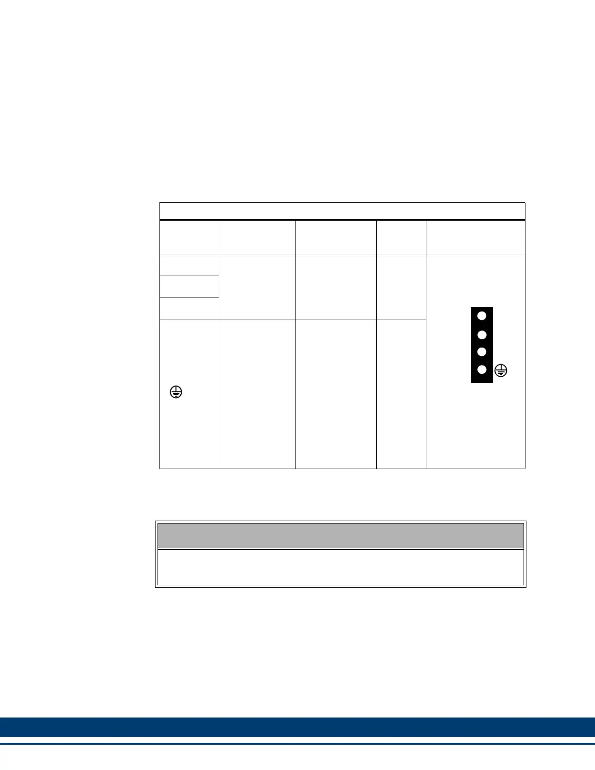
Table 6-19: Pin Assignment for Drive Power Connector
Terminal
Label
Signal Type
Signal
Description
In/Out Pin Sequence
L1
AC Power
200-480VAC
three-phase
power in to
drive.
a
a. May also be used with 100-200VAC, 1 or 3 phase, with limited output capability
In
4-pin Plugable
Screw Terminal
L2
L3
Protective
Ground
Must be con-
nected to Pro-
tective Earth
Ground (SPG).
In
SINGLE PHASE CONNECTION
If single-phase power is used, L1 must be connected to "hot", and L2 must be
connected to "neutral". L3 may remain unconnected.
L1
L2
L3
A
C
P
W
R
 Loading...