Kollmorgen - December 2011 169
MMC Smart Drive Hardware Manual - 460V 3-PHASE MMC SMART DRIVE
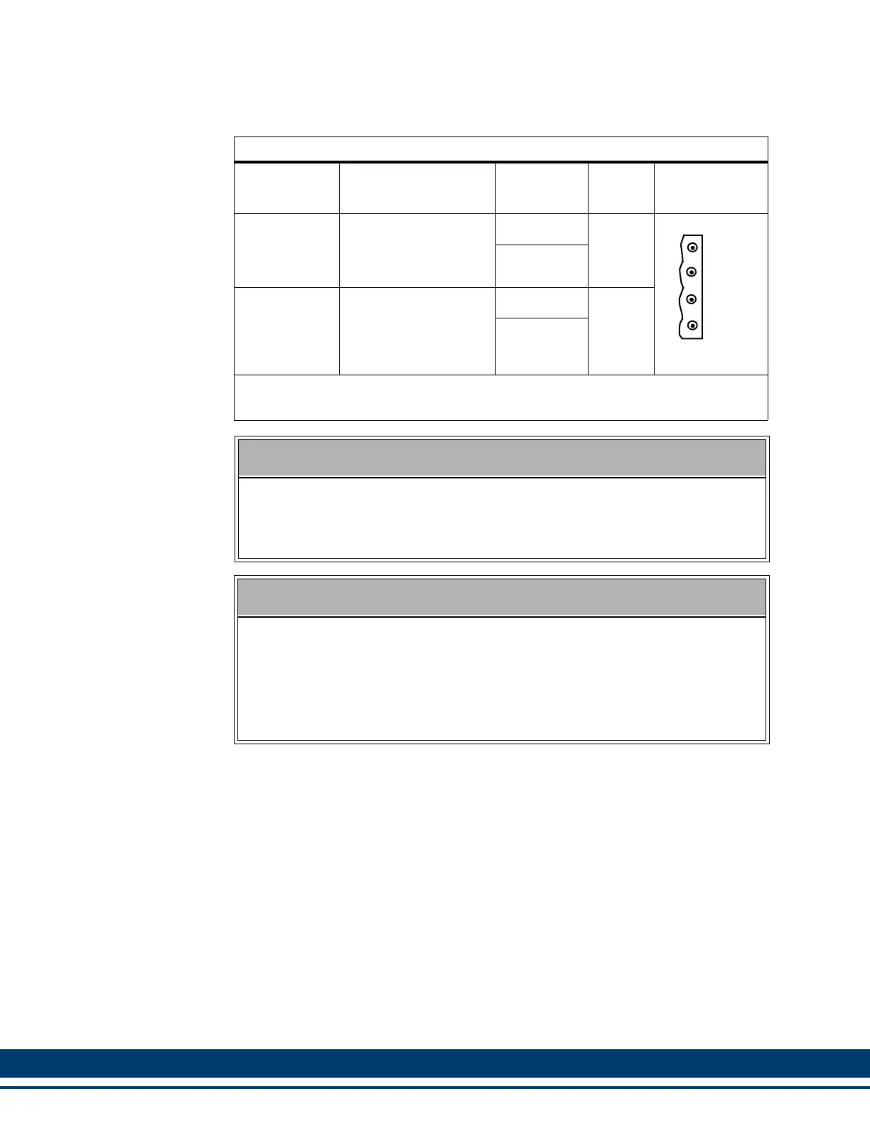
7.2.1.1 Shunt/DC Bus Connector
Table 7-1: 460V Size 1 Shunt/DC Bus Connector
Signal Type Signal Description
Connector
Label
In/Out Connector
Power
External Shunt Resis-
tor. Used to dissipate
energy returned to the
drive by the motor.
Ba-
Out
Ba+
DC Bus Pow-
er
Direct DC bus con-
nection
1C1 (ZK+)
N/A
1D1 (ZK-)
Note: A 4-pin screw-terminal mating connector is included with the drive. Additional
connectors (P/N M.1302.7159) are available from Kollmorgen.
NOTE
The shunt resistor (if installed) across Ba+ and Ba- will be connected across
the DC bus when the DC bus reaches the “shunt switch threshold” as shown
in the specification table; or when the “Shunt On” input on the J1 connector
is active.
NOTE
If a 460V drive is connected to 220V to run a 220V motor, enable the “220V
Shunt on 440V Drive” feature using PiCPro, connect GPOUT3 on the Drive
I/O (IO) connector to the “Shunt On” input on the J1 connector, and install
the appropriate shunt resistor across the Ba+ and Ba- terminals. The shunt
resistor will be applied across the DC bus when the DC bus voltage rises
above 415 volts, and will be removed when the DC bus voltage falls below
400 volts.
Ba-
Ba+
1C1
1D1
 Loading...