288 Kollmorgen - December 2011
MMC Smart Drive Hardware Manual - DRIVE RESIDENT DIGITAL MMC CONTROL
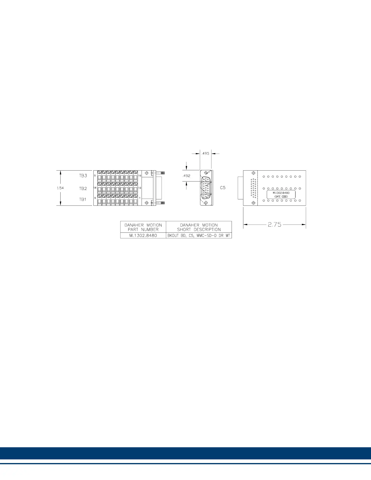
Figure 12-6: General I/O Port Breakout Board Dimensions
12.5.5.1 DC Output Operation
The General I/O Port provides 8 source-only 24 Vdc outputs. These outputs get their
power from Pin 9 of the General I/O connector. Each of the 8 outputs on the general I/
O connector is a solid state switch rated at 250 ma. An example of connecting the DC
Outputs to loads is shown in Figure 12-7.
When a short circuit condition is sensed, all outputs in the group are turned off and
remain off for approximately 100 ms regardless of ladder activity. After 100 ms, the
ladder again controls the outputs. In addition, each output is protected with internal
clamping diodes. Without clamping, high voltage transients (kickback) from inductive
loads might damage the module.
For safety reasons, all outputs turn off (no current flow) when a scan loss condition
occurs.
 Loading...