Kollmorgen - December 2011 73
MMC Smart Drive Hardware Manual - 230V 1/3 PHASE MMC SMART DRIVE
5.1 Control Section Connectors, Switches, LEDs
This section describes the connectors, switches, and LEDs located on the Control
Section (right portion) of the drive.
5.1.1 LEDs
5.1.2 PiCPro Port (Digital Interfaced Drives)
This section details the PiCPro Port connector on the Digital Interfaced Drives (-D and
-DN). For information on the PiCPro Port connector on Analog Interfaced Drives, see
section 5.1.3 on page 75.
The 6-pin circular DIN PiCPro Port connector (labeled “P1” on the front of the Drive)
provides serial communication for the PiCPro programming interface.
• Pin descriptions for are provided in Table 5-2
• Pin assignments are provided in Table 5-3
• The available PiCPro Port to PC cable is described in Table 5-4
NOTE
The functionality and descriptions for the switches, connectors, and LEDs on
the control section of the 460V MMC Smart Drives are the same as those on
the 230V MMC Smart Drive.
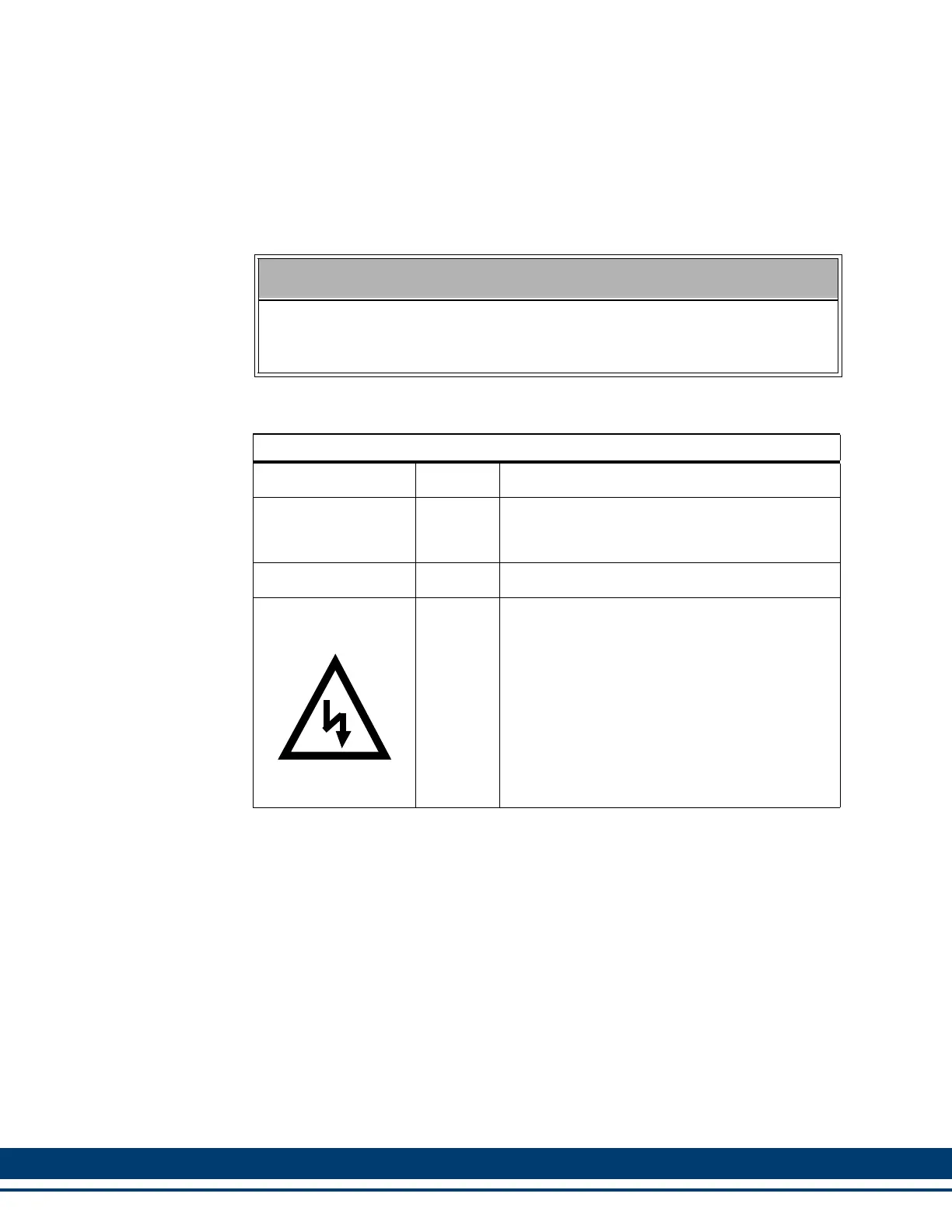
Table 5-1: LEDs Description for 230V MMC Smart Drive
LED Color Description
P Green
Power LED. Indicates when illuminated that
power is being supplied to the 24V input termi-
nal strip.
D1 Yellow Status LED. Drive status and fault information.
DC BUS
Orange
Bus Voltage LED. Indicates when illuminated
that the DC bus is at a hazardous voltage (not
available on 460V Smart Drives).
DANGER
DC bus capacitors may retain hazardous volt-
ages for up to ten minutes after input power has
been removed. Always use a voltmeter to en-
sure that the DC bus voltage is below 50VDC
before servicing the drive. Failure to observe
this precaution could result in severe bodily in-
jury or loss of life.

 Loading...