Kollmorgen - December 2011 281
MMC Smart Drive Hardware Manual - DRIVE RESIDENT DIGITAL MMC CONTROL
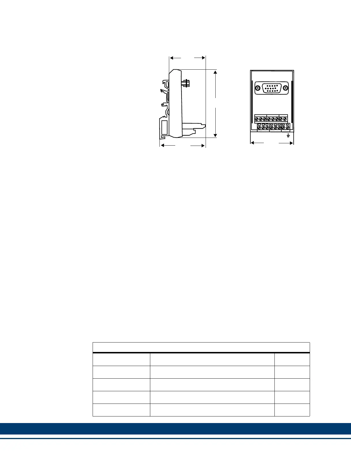
Figure 12-4: User Port Breakout Box Dimensions
12.5.4 Ethernet Port
The 8-pin RJ-45 Ethernet Port connector (labeled “C4” on the front of the Control)
provides IEEE 802.3/802.3u-100Base-TX/10Base T, half duplex connectivity between
an Ethernet device and the Control. Also provided on near the RJ-45 connector is a
green “Link” light (which will be on if there is either a 100Base-T or 10Base-T Link)
and a green “Activity” light (which will be on whenever a send or receive packet has
occurred on the network).
Communication using the Ethernet Port can be between the Control and a PC, User
Interface, or other Ethernet device or network. For example, PiCPro running on a PC
can communicate to the Control through this Ethernet connector.
Typically, a “straight-through” shielded cable should be used when connecting the
Control to another Ethernet device.
• Pin descriptions for are provided in Table 12-14
• Pin assignments are provided in Table 12-15
• The available Ethernet Port to Ethernet Device cables are described in Table 12-
16
Table 12-14: Ethernet Port Pin Descriptions
Function Notes Pin
Receive Data + Receives data from connected device. 3
Receive Data - Receives data from connected device. 6
Transmit Data + Transmits data to connected device. 1
Transmit Data - Transmits data to connected device. 2
1.750”
2.250”
3.000”
1
9
2.250”
8
15
 Loading...