282 Kollmorgen - December 2011
MMC Smart Drive Hardware Manual - DRIVE RESIDENT DIGITAL MMC CONTROL
Shield Ground
Provides a path for shield current through the
chassis to an external single point ground.
Shell
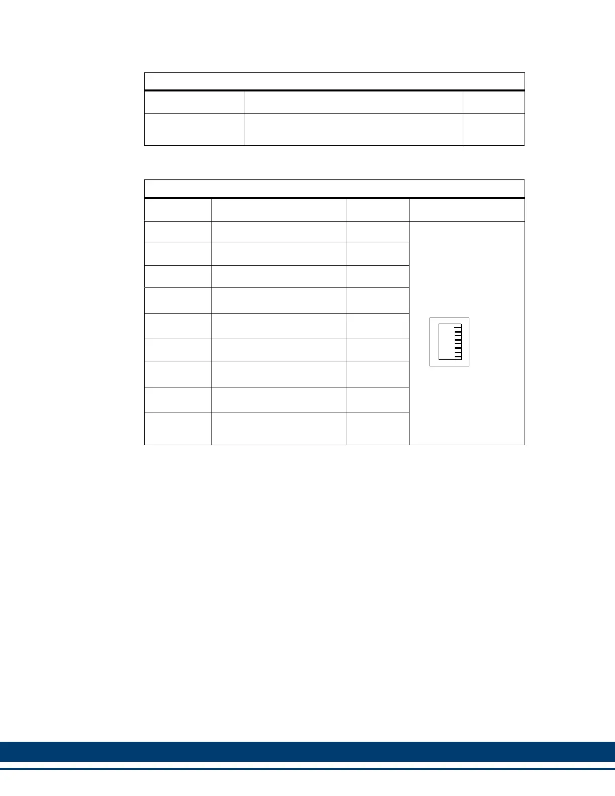
Table 12-15: Ethernet Port Pin Assignments
Pin Signal In/Out Connector Pinout
1 Transmit Data + Out
RJ-45
2 Transmit Data - Out
3 Receive Data + In
4
Termination Resistors
a
a. Pins 4, 5, 7, and 8 are tied to termination resistors on the Control. Standard
Ethernet cables contain 8 wires. The Control only uses 4 of these wires as
shown. Connecting the 4 unused wires to pins 4, 5, 7, and 8, (as will be done in
a standard Ethernet cable) reduces noise that can be induced from the unused
wires to the Transmit and Receive wires.
In
5
Termination Resistors
(a)
In
6 Receive Data - In
7
Termination Resistors
(a)
In
8
Termination Resistors
(a)
In
Connector
Shell
Shield In
Table 12-14: Ethernet Port Pin Descriptions
Function Notes Pin
C4
1
8
 Loading...