Kollmorgen - December 2011 187
MMC Smart Drive Hardware Manual - 460V 3-PHASE MMC SMART DRIVE
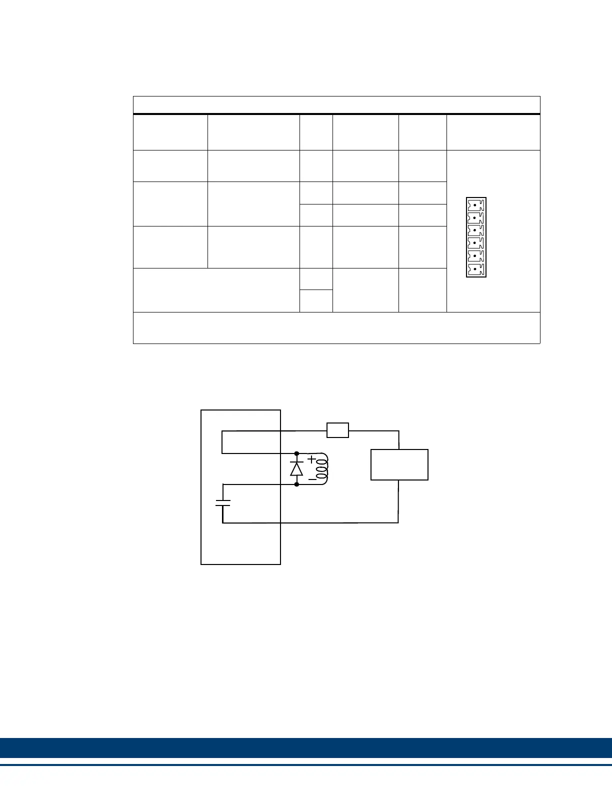
7.2.4.4 Motor Brake Connector (X101)
Figure 7-8: Wiring Example for X101 Connector
Table 7-17: 460V Size 4 Motor Brake Connector (X101)
Signal Type
Signal
Description Pin
Connector
Label In/Out Connector
Power
24 VDC brake in-
put power
1+24VBRKIn
Brake control
Brake connec-
tions
2Brake + Out
3 Brake - In
Power
24 VDC common
(supply and mag-
net)
424VCOMOut
Not Used.
5
N/C
Not
Used
6
Note: A 6-pin cage-clamp mating connector is included with the drive. Additional connec-
tors (P/N M.1302.7099) are available from Kollmorgen.
+24VBRK
Brake +
Brake -
24VCOM
N/C
N/C
Top
1
2
3
4
5
6
BRAKE -
+24VCOM
24V Power
Supply
Brake
24V
+24V
COM
Drive
Connector
4A
BRAKE +
+24VBRK
MOSFET
1N4004
 Loading...