182 Kollmorgen - December 2011
MMC Smart Drive Hardware Manual - 460V 3-PHASE MMC SMART DRIVE
7.2.3.4 Motor Brake Connector (X101)
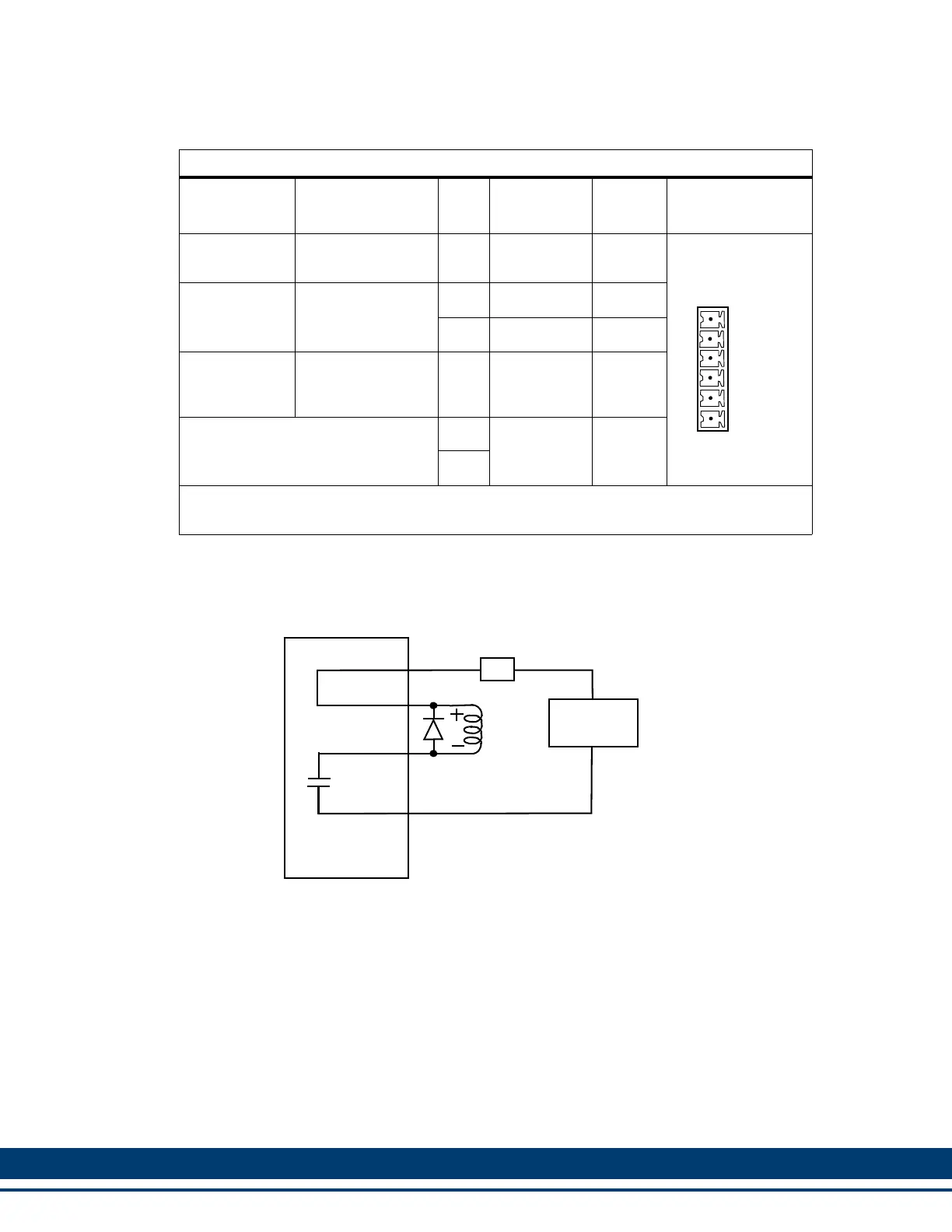
Figure 7-6: Wiring Example for X101 Connector
7.2.4 Size 4 Power Section Connectors
This section describes in detail the connectors located on the Power Section of the
Size 4 drives.
The functionality and descriptions for the switches and connectors on the Control
Section of the 460V MMC Smart Drives are the same as those on the 230V MMC
Smart Drive. Refer to section 5.1 on page 73 for more information.
Table 7-13: 460V Size 3 Motor Brake Connector (X101)
Signal Type
Signal
Description
Pin
Connector
Label
In/Out Connector
Power
24 VDC brake in-
put power
1 +24VBRK In
Brake control
Brake connec-
tions
2 Brake + Out
3 Brake - In
Power
24 VDC common
(supply and mag-
net)
4 24VCOM Out
Not Used.
5
N/C
Not
Used
6
Note: A 6-pin cage-clamp mating connector is included with the drive. Additional connec-
tors (P/N M.1302.7099) are available from Kollmorgen.
+24VBRK
Brake +
Brake -
24VCOM
N/C
N/C
Top
1
2
3
4
5
6
BRAKE -
+24VCOM
24V Power
Supply
Brake
24V
+24V
COM
Drive
Connector
4A
BRAKE +
+24VBRK
MOSFET
1N4004

 Loading...