78 Kollmorgen - December 2011
MMC Smart Drive Hardware Manual - 230V 1/3 PHASE MMC SMART DRIVE
5.1.4 Node Address Rotary Switch (Digital Interfaced MMC-SD Only)
Two rotary switches are used to set the drive address. Rotate the switch to the
desired address.
Addresses can be set to any number from 1 through 64. The top switch represents
values of base ten. The bottom switch represents values of base 1.
As an example, rotating the switch to a setting of 2 on the top switch equals the value
of 20 (2 x 10). Rotating the switch on the bottom switch to a setting of 5 equals the
value of 5. The actual address setting is 25 (20 + 5).
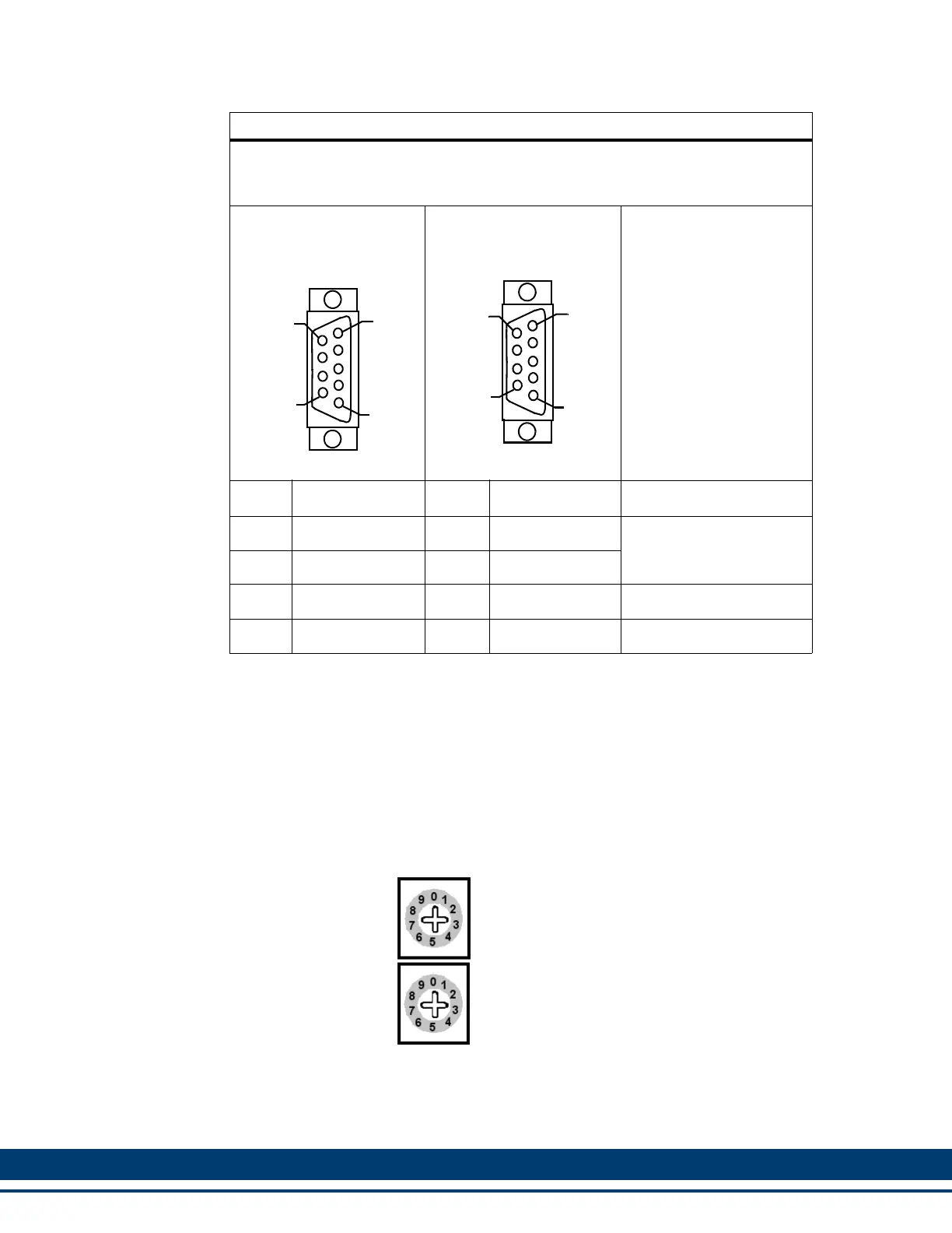
Table 5-7: PiCPr0 Port to PC Cable
Part Number: M.1302.8250
Length: 4 M (13 ft)
Cable type: 24 AWG, shielded, twisted pair, 4 conductor.
9-Pin female D-sub (to
PiCPro Port, face view)
9-Pin female D-sub (to
PC COM Port, face view)
Pin Signal Pin Signal Notes
2 Receive Data 3 Transmit Data Twisted
3 Transmit Data 2 Receive Data Pair
5 Signal Ground 5 Signal Ground
Shell Drain Shell Drain
6
5
9
1
6
5
9
1
10s
1s

 Loading...