130 Kollmorgen - December 2011
MMC Smart Drive Hardware Manual - 460V 3 PHASE MMC SMART DRIVE NEXTGEN
6.1 Control Section Connectors, Switches, LEDs
This section describes the connectors, switches, and LEDs located on the Control
Section (right portion) of the drive.
6.1.1 Status Display
The Status Display is located on the top-front of the drive, and consists of two 7-
segment displays. The Status Display will indicate the Drive’s current operating
condition, including error codes. Refer to the PiCPro Help for the description of the
various display conditions.
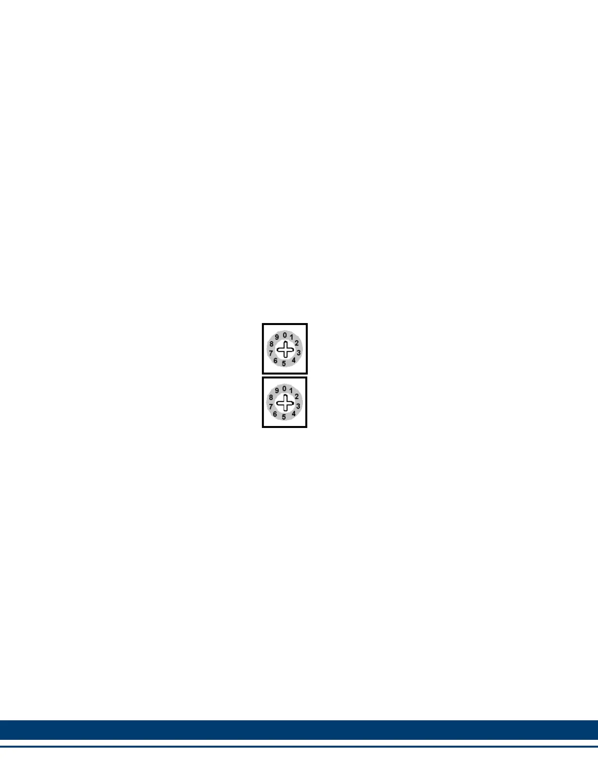
6.1.2 Node Address Rotary Switches
Two rotary switches are used to set the drive address. Rotate the switch to the
desired address.
Addresses can be set to any number from 1 through 64. The top switch (S1)
represents values of base ten. The bottom switch (S2) represents values of base 1.
As an example, rotating S1 to a setting of 2 equals the value of 20 (2 x 10). Rotating
S2 to a setting of 5 equals the value of 5. The actual address setting is 25 (20 + 5).
(10s)
(1s)
S1
S2

 Loading...