152 Kollmorgen - December 2011
MMC Smart Drive Hardware Manual - 460V 3 PHASE MMC SMART DRIVE NEXTGEN
6.2 Power Section Connectors
This section describes the connectors located on the Power Section (left portion) of
the drive.
6.2.1 DC Power Connector
The DC Power Connector consists of a plugable 3-pin screw-terminal block, and
provides +24VDC (nominal) Logic Power to the drive, as well as the "Safe Torque Off"
Enable signal.
6.2.1.1 "EN" requirements and Safe-off Operation
The Drive contains Safe-off capability.The "EN" pin located on the 3-pin DC PWR
connector must have 24Vdc applied to it in order for the drive to operate.
The following two sections describe the behavior of Safe-off function.
6.2.1.1.1 "EN" Operation
The Drive will only perform a Safe-off fault if the following two conditions are met:
• The drive is enabled by the application
• The "EN" input pin is not at 24Vdc
The general sequence of operation of the Safe-off function is as follows:
1. An external user-supplied circuit provides 24Vdc to the "EN" input
2. The drive is enabled via the Application Program
3. The application controls the motor as desired
4. The drive is disabled via the Application Program
5. The external user-supplied circuit removes 24Vdc from the "EN" input
6. The process is repeated starting with step 1 above as required
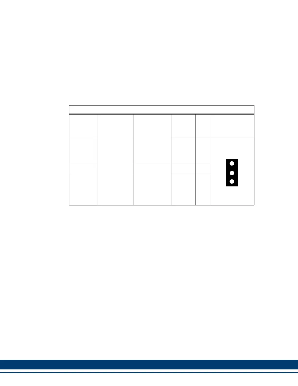
Table 6-18: Pin Assignment for 24 VDC IN/Brake Connector
Terminal
Label
Signal Type
Signal
Description
PiCPro
I/O
Label
In/
Out
Connector
Pinout
+24V Logic Power
+24V user
supplied pow-
er signal termi-
nal.
N/A In
3-pin Plugable
Screw Terminal
COM Common +24V Common N/A In
EN Drive Enable
Safe-off Sig-
nal. (See sec-
tion 6.2.1.1 on
page 152).
N/A In
+24V
COM
EN
D
C
P
W
R

 Loading...