Kollmorgen - December 2011 171
MMC Smart Drive Hardware Manual - 460V 3-PHASE MMC SMART DRIVE
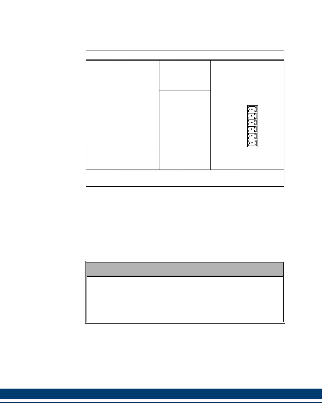
7.2.1.4 24V Power Connector (J1)
Table 7-4: 460V Size 1 24V Power Connector (J1)
Signal
Type
Signal
Description
Pin
Connector
Label
In/Out Connector
Power
24 VDC input
power
1 +24V
In
Top
2 +24V
24V Logic
Input/Out-
put
See footnote
a
a. As an Output, indicates that the AC Input Power to the drive is OK. As an Input,
instructs the drive to run even though AC Input Power is not present. This is typ-
ically used when two drives share bus power that is provided by the drive con-
nected to AC Input Power. See section A.1 on page 301 for more information.
3 Mains On In/Out
24V Logic
Input/Out-
put
See footnote
b
b. As an Output, indicates that the drive’s Shunt Output is active. As an Input,
instructs the drive to activate its Shunt Output. Whenever the Shunt On signal is
active (24Vdc nominal), the user-supplied shunt resistor (installed between Ba+
and Ba-) is connected across the DC bus. See section A.1 on page 301 for
more information.
4 Shunt On In/Out
Power
24 VDC input
common to the
drive.
5 24V Com
In
6 24V Com
Note: A 6-pin cage-clamp mating connector is included with the drive. Additional
connectors (P/N M.1302.7099) are available from Kollmorgen.
CAUTION
A possible ignition hazard within the MMC 460V Smart Drives exists if exces-
sive current is drawn from the 24 VDC powering the MMC Smart Drive. To
prevent this possibility (due to improper wiring or 24 VDC supply failure), a
fuse should be used in series with the 24 VDC to the MMC Smart Drive (4 A
max). In addition, the 24 VDC shall be supplied by an isolating source such
that the maximum open circuit voltage available to the MMC Smart Drive is
not more than 30 VDC.
+24V
+24V
Mains On
Shunt On
24 Com
24 Com
1
2
3
4
5
6
 Loading...