Kollmorgen - December 2011 33
MMC Smart Drive Hardware Manual - INSTALLING THE MMC SMART DRIVE
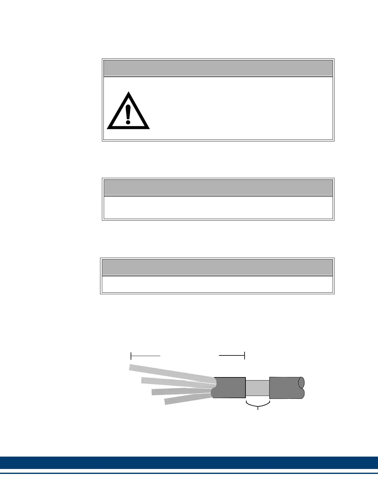
3.13.4 Preparing Motor Connection Wires
1. Strip back cable jacket approximately 152 mm (6.0 in.) from the end of the cable.
2. Strip approximately 12 mm (0.50 in.) of insulation from the end of each conductor.
Do not tin ends after stripping.
3. Strip the cable jacket away from the cable until the shield braid is visible. Expose
17 mm (0.68 in.) of cable shield braid.
Figure 3-3: : Motor Cable
4. Attach the individual wires from the motor cable to their assigned terminal. Refer
to Chapters 5 and 6 for front panel connectors and terminal assignments.
5. Tighten each terminal screw.
WARNING: FEEDBACK DEVICE DAMAGE
Feedback Cable Installation and Removal
All power to the Smart Drive (24 Vdc and main AC power) must
be removed before connecting/disconnecting feedback cable
connectors at the Smart Drive (F1 and F2 connector) or at the
motor feedback device. Also, all connections must be secure
when power is applied. Failure to follow these precautions may
result in damage to the feedback device or Smart Drive.
NOTE
It is recommended that Kollmorgen cables be used. Kollmorgen cables are
designed to minimize EMI and are recommended over hand-built cables.
IMPORTANT
Do not nick, cut or damage wire strands while removing wire insulation.
Expose 17 mm (0.68 in.) of braid
(1U2)
Ground
Dimension varies
by Drive Model
(1V2)
(1W2)
 Loading...